Transcription of Transformer Protection Application Guide - IEEE
1 Transformer ProtectionApplication GuideAbout the AuthorGeorge Rockefeller is President of Rockefeller Associates, Inc. He has a BS in EE from Lehigh University,a MS from New Jersey Institute of Technology, and a MBA from Fairleigh DickinsonUniversity. Mr. Rockefeller is a Fellow of IEEE and Past Chairman of IEEE Power Systems RelayingCommittee. He holds nine Patents and is co-author of Applied Protective Relaying (1st Edition).Mr. Rockefeller worked for Westinghouse Electric Corporation for twenty-one years in Application andsystem design of protective relaying systems. He worked for Consolidated Edison Company for ten yearsas a System Engineer. He has also served as a private consultant since the GuideThis Guide contains a summary of information for the Protection of various types of electrical Basler Electric Company nor anyone acting on its behalf makes any warranty or representation,express or implied, as to the accuracy or completeness of the information contained herein, nor assumesany responsibility or liability for the use or consequences of use of any of this issue date 05/96 Revised 05/99, John Boyle; small updatesRevised 08/03, Larry Lawhead; small updatesRevised 04/07, John Horak; extensive rewriteRevised 06/07, John Horak; minor typographical and editorial corrections1 Transformer ProtectionApplication GuideThis Guide focuses primarily on Application ofprotective relays for the Protection of powertransformers, with an emphasis on the mostprevalent Protection schemes and are emphasized.
2 Setting proceduresare only discussed in a general nature in thematerial to follow. Refer to specific instructionmanuals for your relay. The references provide asource for additional theory and engineer must balance the expense ofapplying a particular Protection scheme againstthe consequences of relying on other protectionor sacrificing the Transformer . Allowing a pro-tracted fault would increase the damage to thetransformer and the possibility of tank rupturewith a consequent oil fire and consequentpersonnel safety risks. There is no rule that sayswhat specific Protection scheme is appropriatefor a given Transformer Application . There issome tendency to tie Protection schemes to theMVA and primary kV of a Transformer . Whilethere is some validity to this approach, there aremany other issues to be considered. Issues tobe considered include: The severity of personnel safety concernsand the possibility that a given protectionscheme can reduce these risks. The danger to nearby structures and pro-cesses if a Transformer fails catastrophicallyand the possibility that a given protectionscheme can reduce the possibility of such afailure.
3 An overall view of the economic impact of atransformer failure and what can be done toreduce the risk, including: The direct economic impact of repairingor replacing the Transformer . The indirect economic impact due toproduction loss. Repair time vs. complete replacementtime. The availability of backup power feed oremergency replacement transformers , andthe cost of each option. The possibility that a given protectionscheme can reduce the damage andresultant repair time, or that it can changea replacement into a specific applications that affect protectionare: A tap changer flashover can ordinarily berepaired in the field, but if this fault is allowed toevolve into a winding fault, the Transformer willneed to be shipped to a repair facility; hence, Protection that can rapidly sense a tap changefault is desirable. A high magnitude through fault(external fault fed by the Transformer ) shakes andheats a Transformer winding, and the longer thethrough fault lasts, the greater the risk of itevolving into an internal Transformer fault; hence,fast clearing for close-in external faults is part ofthe Transformer Protection scheme.
4 Sometransformers are considered disposable andreadily replaced, reducing the need for ad-vanced Protection schemes. Transformer protec-tion commonly includes some coverage of2external bus and cable, and faults in these zonesmay expose personnel to arc flash hazards. Slowclearing Protection schemes may be unaccept-able from an arc flash exposure in an indoor Transformer may have high riskof catastrophic facility damage and even higherpersonnel safety risks, increasing the need foradvanced high speed Protection . The proximityof flammable process chemicals increases aneed for Protection schemes that reduce the riskof a tank fire. The failure of a Transformer used ina large base load unit-connected generator maycause extended generation-replacement costs;even the loss of a small station service trans-former can cause a notable disruption of genera-tion and high economic consequences. Similareconomic impacts may also exist at industrialsites. Some transformers are custom designsthat may have long lead times, increasing theneed for advanced Protection Failure StatisticsTable I lists failures for six categories of faults(IEEE , Guide for Protective RelayApplications to Power transformers , Ref.)
5 1).Winding and tap changers account for 70% offailures. Loose connections are included as theinitiating event, as well as insulation failures. Themiscellaneous category includes CT failure,external faults, overloads, and damage inshipment. An undisclosed number of failuresstarts as incipient insulation breakdown prob-lems. These failures can be detected by sophis-ticated online monitoring devices ( gas-in-oilanalyzer) before a serious event I - Failure Rates, Ref. 1. 1955-1965 1975-1982 1983-1988 Percent of Percent of Percent of Number Total Number Total NumberTotalWinding failures134516155514437 Tap changer failures4919231218522 Bushing failures4115114104211 Terminal board failures197716133 Core failures7324241 Miscellaneous failures12572610126 TOTAL26210011271003891002. Protection Example and General ConceptsThe reader interested in additional information,advanced or unusual Application advice, anddetailed settings guidance should refer to Ref.
6 Document includes extensive references andbibliographies. Also, Ref. 2 and 3, textbooks onprotective relaying, contain chapters on trans-former Protection , and Ref. 4, another IEEE standard, includes good overall protectionschemes where a Transformer is the interfacepoint between a utility and an industrial are three general categories of protectiverelay technology that arise in the discussions tofollow: Electromechanical: uses magnetic fluxcreated from current and voltage to createtorques on movable disks and relays, whichis the source of the term relay. Usuallysingle device number functionality. Solid State: uses low voltage analog signalscreated from sensed currents and voltages;uses discrete electronics and basic logiccircuits; may contain a basic microprocessorfor logic and some math. Usually single ordual device number functionality. Numeric: a multifunction, programmablelogic relay; digitizes sensed current andvoltage, then calculates an RMS or phasorequivalent value; uses a high-end micropro-cessor.
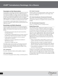
7 Usually incorporates many devicenumber Basler Electric relays are solid state II lists some common ANSI device num-bers associated with Transformer Protection . Anumeric relay generally contains many imple-mentations of these devices within its program-ming, and each instance of a device is referredto, herein, as an element in the relay. Forexample, while the Basler BE1-CDS220 isprimarily a Transformer differential relay (hence,includes the 87 device in elements named 87 Pand 87N), it also includes nine independentimplementations of the 51 overcurrent device,called the 51P, 151P, 251P, 51Q, 151Q, 251Q,51N, 151N, and 251N elements as well as manyother device 1 shows extensive use of relays thatwould be representative of a large industrialload. This will be used for discussions in some ofthe material that follows. There are two 115 kVfeeds to two 30 MVA transformers that areresistance grounded on the 13 kV side, limitingground fault current to about 400A from eachtransformer.
8 In other applications , a reactor isused, and in some applications , the ground faultcurrent is limited to less than 10A. In a typicalutility Application , transformers are connecteddirectly to ground, but occasionally a smallreactor is placed in the Transformer neutral thatlimits ground fault current to approximately thesame level as three phase faults. In this examplesystem, the Protection scheme describedapplies to solidly grounded (as well as imped-ance grounded) systems, except the effect ofground impedance results in the addition ofprotection functions not required on a solidlygrounded phase and ground differential (87P and 87N,Section 4) and sudden pressure relay (63,Section 6) provide the primary Transformer faultprotection. The suite of overcurrent elements(51, Section 8) is generally considered backuptransformer Protection , or for Protection of thebus and backup Protection for the feeder elements are part of the transformerprotection in that they limit the accumulateddamage that occurs from a Transformer feedinghigh current into downstream faults.
9 The 67 Nrelay offers an alternative to the 87N spot monitoring (49, Section 9) is indicated,but is likely an alarm only there is a possibility of over voltage on theunits due to local generation or a transformerbeing placed at the end of a long line (the Feranti effect), voltage relays (24 and 59,Section ) may be included. Another pos-sible backup Protection scheme is low voltage(27) or unbalanced voltage detection (47). Ifthere is local generation, to help detectislanding conditions an over/under frequency(81, O/U) relay may be installed, though an 81may not be considered a Transformer overcurrent relays and directionalpower (67/50, 67/51, and 32, respectively,Section ) respond to load current circulatingthrough the 13 kV buses when the 115kVbreaker A is open and the tie is elements may also respond to faults in thetransformer near the secondary bushings. If thetransformers can be operated in parallel, theelements also provide a means to sense tapchangers that have become out of step with oneanother.
10 If there is generation in the , sensitive 67 elements can sense a smallgenerator backfeeding a 115kV primary and secondary relaying wouldsometimes be configured to feed their ownlockout relays (86) to help ensure that protectionis available even with a failure of one 86 relay orits dc Protection scheme in does not utilizefuses. Fuses normally would be seen only onlower MVA transformers than indicated. SeeSection of the indicated MVA normallywould have their oil tested for dissolved gasses(Section 7) as part of routine transformers may have continuous on-linemonitoring III and IV (pages 29-30) provide BaslerElectric relay models and their device 1 - Protection Example5 DeviceDescriptionComment24 Volts/HzFor overexcitation detection. Similar to 59 but the pickup is proportionate an inverse time = line to line27lnln = line to neutral (or line to ground. Note neutral may be isolated from ground insome systems.)32 Power ElementUsed to sense power backfeed through transformer47 NegativeUsually defined by: V2 = (Van+a2 Vbn+aVcn)/3.

![IEEE 383 White Paper (002).pptx [Read-Only]](/cache/preview/0/2/e/4/a/4/f/b/thumb-02e4a4fb7dcfb58ad21178aee0a30554.jpg)