Transcription of Translation of ER -diagram into Relational Schema
1 Translation of ER -diagram into Relational Schema Dr. Sunnie S. Chung CIS430/530. Learning Objectives Define each of the following database terms Relation Primary key Foreign key Referential integrity Field Data type Null value Discuss the role of designing databases in the analysis and design of an information system Learn how to transform an entity-relationship (ER). Diagram into an equivalent set of well-structured relations 2. 3. 4. 5. Process of database Design Logical Design Based upon the conceptual data model Four key steps 1. Develop a logical data model for each known user interface for the application using normalization principles.
2 2. Combine normalized data requirements from all user interfaces into one consolidated logical database model 3. Translate the conceptual E-R data model for the application into normalized data requirements 4. Compare the consolidated logical database design with the translated E-R model and produce one final logical database model for the application 6. 7. Relational database Model Data represented as a set of related tables or relations Relation A named, two-dimensional table of data. Each relation consists of a set of named columns and an arbitrary number of unnamed rows Properties Entries in cells are simple Entries in columns are from the same set of values Each row is unique The sequence of columns can be interchanged without changing the meaning or use of the relation The rows may be interchanged or stored in any sequence 8.
3 Relational database Model Well-Structured Relation A relation that contains a minimum amount of redundancy and allows users to insert, modify and delete the rows without errors or inconsistencies 9. Transforming E-R Diagrams into Relations It is useful to transform the conceptual data model into a set of normalized relations Steps 1. Represent entities 2. Represent relationships 3. Normalize the relations 4. Merge the relations 10. Refining the ER Design for the COMPANY database Change attributes that represent relationships into relationship types Determine cardinality ratio and participation constraint of each relationship type 11.
4 ER Diagrams, Naming Conventions, and Design Issues 12. Design Choices for ER. Conceptual Design Model concept first as an attribute Refined into a relationship if attribute is a reference to another entity type Attribute that exists in several entity types may be elevated to an independent entity type Can also be applied in the inverse 13. Alternative Notations for ER Diagrams Specify structural constraints on Relationships Replaces Cardinality ratio (1:1, 1:N, M:N) and single/double line notation for Participation constraints Associate a pair of integer numbers (min, max).
5 With each participation of an entity type E in a relationship type R, where 0 min max and max 1 14. Cardinality Ratio (1:1, 1:N, M:N). since name dname 1:N :Each dept has at most one manager on ssn lot did budget Manages. Employees Manages Departments Translation to Relational model? 1-to-1 1-to Many Many-to-1 Many-to-Many 15. 16. Transforming E-R Diagrams into Relations The primary key must satisfy the following two conditions a. The value of the key must uniquely identify every row in the relation b. The key should be nonredundant 17. 18.
6 Transforming E-R Diagrams into Relations Represent Relationships Binary 1:N Relationships Add the Primary key attribute (or attributes) of the entity on the one side of the relationship as a Foreign key in the relation on the other (N) side The one side migrates to the many side 19. 20. Transforming Binary 1:N. Relationships into Relations Relationship: CREATE TABLE ORDER(. CUSTOMER Places ORDER(s) Order_Number CHAR(1), ORDER Table BEFORE Order_Date DATE, Relationship: Promised_Date DATE, (Order_Number, Customer_ID CHAR(1), Order_Date, Promised_Date) PRIMARY KEY.)
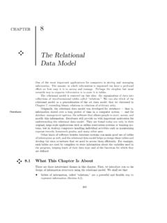
7 ORDER Table AFTER (Order_Number), Relationship: FOREIGN KEY (Customer_ID). (Order_Number, REFERENCES. Order_Date, Promised_Date, CUSTOMER);. Customer_ID). 21. Transforming E-R Diagrams into Relations Binary or Unary 1:1. Three possible options the primary key of A as a foreign key of B. the primary key of B as a foreign key of A. 22. Transforming E-R Diagrams into Relations Represent Relationships Binary and higher M:N relationships Create another relation and include primary keys of all relations as primary key of new relation 23. 24. Constraints on Binary Relationship Types Cardinality ratio for a binary relationship Specifies maximum number of relationship instances that entity can participate in Participation Constraint Specifies whether existence of entity depends on its being related to another entity Types: total and partial 25.
8 Attributes of Relationship Types Attributes of 1:1 or 1:N relationship types can be migrated to one entity type For a 1:N relationship type Relationship attribute can be migrated only to entity type on N-side of relationship For M:N relationship types Some attributes may be determined by combination of participating entities Must be specified as relationship attributes 26. Weak Entity Types Do not have key attributes of their own Identified by being related to specific entities from another entity type Identifying relationship Relates a weak entity type to its owner Always has a total participation constraint 27.
9 Transforming E-R Diagrams into Relations Unary 1:N Relationships Relationship between instances of a single entity type Utilize a recursive foreign key A foreign key in a relation that references the primary key values of that same relation Unary M:N Relationships Create a separate relation Primary key of new relation is a composite of two attributes that both take their values from the same primary key 28. 29. Transforming Unary 1:N. Relationships into Relations Relationship: CREATE TABLE. EMPLOYEE (Manager) EMPLOYEE(. Manages EMPLOYEE Emp_ID CHAR(1), EMPLOYEE Table Name Varchar(30), BEFORE Relationship: Birthday DATE, (Emp_ID, Name, Mgr_ID CHAR(1), Birthday) PRIMARY KEY (Emp_ID), EMPLOYEE Table AFTER FOREIGN KEY (Mgr_ID).)
10 Relationship: REFERENCES. (Emp_ID, Name, EMPLOYEE);. Birthday, Mgr_ID). 30. Transforming Unary M:N. Relationships into Relations Relationship Contains: CREATE TABLE CONTAINS (. ITEM Contains ITEM Containing_Item_Num CHAR(10), 1. Create Table for Relationship Contained_Item_Num CHAR(10), CONTAINS Quantity Integer, PRIMARY KEY. 2. Add PK of each side of (Containing_Item_Num, Tables ( ITEM, ITEM) as Contained_Item_Num), Foreign Keys FOREIGN KEY. 3. Make composite of both (Containing_Item_Num). attributes as Primary Key of REFERENCES ITEM, the Table CONTAINS: FOREIGN KEY.