Transcription of Transmission Lines and SWR - Part V
1 1 More on Transmission Lines and SWR part V By Don Steinbach, AE6PM The first four articles in this series were designed to provide some background definitions and equations as they apply specifically to Transmission Lines and SWR. There aren t any scientific breakthroughs there it s all based on information that s been around for years. The remainder of this series will focus on applying this information to real world situations. Practical Considerations The effort expended working on an antenna trying to drive the SWR down could often be better spent just making contacts instead. Bear in mind that a 1 dB change in signal level is, by definition, the minimum perceptible change in other words, the smallest change that your ear can detect. Your receiver S-meter is designed so that a 6 dB change is one S-unit (more or less) or a 4x change in power, so a 3 dB increase or decrease (2x in signal power) is one-half of one S-unit.
2 That s not to say that an extra dB or two wouldn t help to snag that rare station, but let reality and common sense be your guide. The total loss in dB for a mismatched Transmission line is: TMLL = 10 log [(a2 - | 2|) / (a(1-| 2|))] Where: a = 10ML/10 = 10 ^ (ML/10) | | = (SWR 1)/(SWR + 1) TMLL = Total mismatched line loss ML = Matched- line loss of the Transmission line in dB SWR = SWR at the load ( antenna ) (Ref: ARRL Handbook for Radio Communications, 88th Edition, page ) The additional Transmission line loss for various matched- line loss and SWR at the antenna is shown in Table 1. The format is the same as Table 1 in part 4, so the two can be used together to relate matched- line loss, SWR at the antenna , SWR at the transmitter, and additional Transmission line loss. Adding the matched- line loss to the additional Transmission line loss in Table 1 below yields the total Transmission line loss.
3 For example, if the matched- line loss is 2 dB and the SWR at the antenna is 4, the additional line loss due to SWR is dB and the total Transmission line loss is dB. Looking back at Table 1 in part 4, the same 2 dB matched- line loss and SWR at the antenna of 4 shows a SWR of at the transmitter. Finally we can see all of the effects of loss in the Transmission line . Table 1 Additional Transmission line loss for various matched- line loss and SWR at the antenna . 2 Matched - line Loss dB 1 dB 2 dB 3 dB 4 dB 5 dB 6 dB SWR at antenna Additional line Loss Due to SWR 1 2 3 4 5 6 7 8 9 10 Sanity Check SWR readings can be counterintuitive. Consider the case of a ground-mounted -wave vertical antenna . Here a 50-ohm SWR of 1 isn t necessarily a good thing.
4 You start with the vertical radiator and add a few radials and the feed point impedance is about 50 ohms and the SWR is 1. All is well, or is it? You know that as you add more radials the effect of the lossy ground under the antenna is reduced, the antenna efficiency is improved and the take-off angle becomes lower all good things. But, as you add more radials, the SWR increases until with 120 radials the SWR is about because the feed-point impedance is now about 35 ohms instead of 50 ohms as the antenna configuration approaches its theoretical best (over an infinite ground plane). In this instance, the lowest SWR occurred with the worst-case ground system because the 15-ohm loss in the ground system when added to the 35-ohm radiation resistance of the antenna makes the total feed-point impedance 50 ohms, but 30% of the transmitter power was wasted on the earthworms. Similarily, the feed point impedance of a half-wave dipole antenna varies with its height above ground and its proximity to other conductors.
5 It ranges from a low of about 10 ohms (over a perfectly conducting ground) or 45 ohms (over average real earth) to a maximum of nearly 100 ohms (Ref: ARRL Handbook for Radio Communications, 88th Edition, page ). So, a SWR of 2 referred to 50 ohms for a half-wave dipole is within normal bounds. Extremely short antennas, compared to the wavelength, such as car antennas for HF mobile can have very low radiation resistance, on the order of a few ohms, so the SWR referenced to 50 ohms and measured at the antenna feed point will be very high (maybe 10 to 50 or more) and if it isn t, there is reason to believe that there is a large loss somewhere in the system, probably in the ground path. 3 It s always best to know what you re trying to measure and what to expect in order to avoid reaching erroneous conclusions. SWR Facts There are misconceptions about the effects of standing waves on the Transmission line .
6 Here are some facts: 1. High SWR doesn t cause interference to other electronic devices because SWR by itself doesn t generate new signals. 2. High SWR doesn t cause the Transmission line to radiate. 3. High SWR doesn t cause RF in the shack. 4. High SWR can result in component damage caused by large voltages or currents. 5. High SWR isn t necessarily bad if loss in the Transmission line isn t eating up your power. 6. A SWR of 2:1 at the antenna can be cause for concern on VHF and UHF because of the typically high Transmission line loss at these frequencies. 7. A SWR of over 3:1 at the antenna on HF is usually not a cause for concern if quality coax 100 feet or less in length is used, since the Transmission line loss is usually low. 8. A SWR of 100:1 or more at the antenna on HF is usually not a cause for concern if open-wire Transmission line is used because the loss in the Transmission line is so low.
7 There may be high voltages present, however. 9. SWR is a measure of reflected power, not lost power. 10. SWR can be measured with simple equipment easily built by the average person. 11. Most solid-state transceivers will begin reducing their output power when the SWR exceeds 2:1. 12. Most automatic antenna tuners can only accommodate a limited range of SWR due to practical voltage and current limitations. 13. Reflections, the very nature of standing waves, can adversely affect signal quality since the receiver will receive the same signal multiple times at ever decreasing amplitudes. This could be an issue with some digital modes, causing intersymbol interference. The SWR Meter Since you ve read many words about SWR to this point, some insight into how to measure SWR is in order. SWR meters are often seen at swap meets priced at $10 to $25. Older manufacturers include Heath, Knight, Swan, EF Johnson, Calrad and RadioShack.
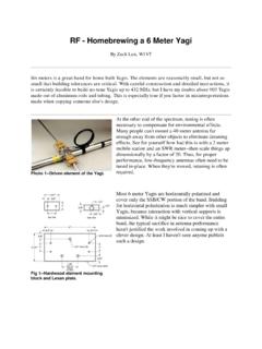
8 See Fig. 1 for some examples. You can also build your own. 4 . Typical SWR meters Found at Swap Meets. Clockwise from left, the Heathkit AM-2, Swan SWR-1A Yaesu YS-500, Heathkit HM2140A and the Micronta 21-520A. The basic SWR meter consists of a sampling line (aka directional coupler) that provides a sample of the forward and reflected power from the main Transmission line . That and a rf wattmeter to measure the sampled forward and reflected power is all that you need. The parts to build the directional coupler will only cost a couple of dollars. The only problem with this approach is that the rf wattmeter will set you back a few hundred dollars. The solution to the rf wattmeter issue is to convert the rf power measurement to a dc voltage that can be measured with an inexpensive panel meter or a multimeter that you probably already own. This takes two diodes, two resistors and two capacitors for a total cost of less than a dollar.
9 The sampling line (directional coupler) can be constructed several different ways: (1) two parallel Lines in a 3-sided trough approximating a section of coax cable, (2) a section of coaxial cable with a small insulated wire threaded under the cable shield, (3) stripline constructed on a etched circuit board, and (4) a toroidal core usually ferrite - with a few turns of wire wound on it with the Transmission line center conductor passing through it. The latter is the simplest to build mechanically and is widely used. See Figures 2A through 2C for a view of some different construction methods. 5 Fig. 2A. The Heathkit AM-2 uses a brass tube center conductor with two parallel sampling Lines in a u-shaped trough. See Fig. 3 for the schematic diagram. 6 Fig. 2B. The Heathkit HM2140A uses a toroid winding with a single wire through the center as a sampling circuit. See L101 in the photo. The vertical white wire connects the input and output coax connectors and the toroid winding senses the forward and reflected power.
10 Fig. 2C. The Elecraft CP1 is a true directional coupler with sense windings for the forward and reverse directions. This is available in kit form. See the Transmission line Signal Sampling article in the December 2009 SCCARA-GRAM for information on the design of the toroidal transformers. A typical SWR meter circuit is shown in Figure 3. The SPDT switch selects the dc voltage to the meter from the diodes connected to the two sampling Lines , one for the forward (incident) wave and the other for the reflected wave. Some units use two meters , eliminating the switch. The crossed-needle dual-movement single meter approach is also popular, although I find it difficult to read with any accuracy. Regardless of any enhancements or bells and whistles, all SWR meters are based on the concept in Fig. 3. 7 Fig. 3. Schematic diagram of the Heathkit AM-2 SWR meter. The antenna Analyzer The antenna analyzer is a useful instrument for characterizing a Transmission line .