Transcription of TRENCHING & SHORING GUIDELINES - TAMUC
1 TRENCHING & SHORING GUIDELINES DEPARTMENT OF RISK MANAGEMENT AND SAFETY CREATED JUNE 2009 Table of Contents Introduction .. 1 Requirements .. 1 Excavations .. 2 SHORING Types .. 2 Hydraulic SHORING .. 2 Pneumatic SHORING .. 2 Screw Jacks .. 2 Single-Cylinder Hydraulic Shores .. 3 Underpinning .. 3 Shielding Types .. 3 Trench Boxes .. 3 Combined Use .. 3 Slope and Shield Configurations.. 4 Sloping and Benching .. 4 Sloping .. 4 Slope Configurations .. 5 5 Determination of Soil Type .. 6 Stable Rock .. 6 Type A Soils .. 6 Type B Soils .. 6 Type C Soils .. 6 Soil Testing Methods .. 7 Visual Test .. 7 Manual Tests .. 7 Soil Mechanics .. 8 Safety and Health Considerations .. 9 Competent Person .. 9 Surface Crossing of Trenches .. 9 Ingress and egress .. 9 Exposure to Vehicles .. 10 Exposure to Falling Loads .. 10 Warning Systems for Mobile Equipment.
2 10 Hazardous Atmospheres and Confined Spaces .. 10 Emergency Rescue Equipment .. 11 Standing Water and Water Accumulation .. 11 Inspections .. 11 Definitions .. 12 1 | P a g e Introduction The following procedures will apply to all Texas A&M University-Commerce employees and contractors. A trench excavation is a narrow excavation made below the surface of the ground where the depth is greater than the width, but the width of a trench (measured at the bottom) is less than 15 feet. This program is established to assist A&M Commerce staff to recognize the hazards involved in TRENCHING in order to prevent injury. Hazards associated with excavation include: cave-ins striking of underground utilities falling tools, materials, and equipment hazardous air contaminants or oxygen-deficient environments Requirements All A&M Commerce employees and contractors are to comply fully with the following requirements: A competent person shall be placed in charge of all excavations.
3 All materials in proximity to the excavation site must be stored, arranged, or secured in such a manner as to prevent the material from accidentally falling into the trench. The Department or Contractor Supervisor is responsible to ensure underground utilities are located prior to excavation work. While the excavation is open, the underground utilities must be protected, supported, or removed as necessary. Employees are not are allowed in the excavation while heavy equipment is digging. Adequate means of egress will be maintained at all times. Excavations located near public traffic shall be barricaded and employees shall be provided with and wear warning vests. In excavations greater than four (4) feet in depth, or where oxygen deficiency or other hazardous atmospheres could reasonably be expected to exist, testing must be performed prior to the entry of employees.
4 If a hazardous atmosphere is verified at a TRENCHING site, emergency rescue equipment must be available and attended (SCBA, Lifelines, etc.) as required by the TAMUC Confined Space Program. Inspection of TRENCHING operations for hazardous conditions must be performed daily or when changing conditions warrant (rain, different soil type, etc.). Upon detection of a hazardous condition employees must be removed from excavation at once. Both visual and manual soil testing will be performed by a "competent person" to determine soil type before employees are allowed to enter a trench. Protective systems for excavations deeper than 20 ft. shall be designed by a registered engineer. Excavation beneath the level of adjacent foundations, retaining walls, or other structures must be avoided unless specific regulatory requirements for that type of activity have been met.
5 2 | P a g e Excavations All excavations or trenches of 4' or greater in depth shall be appropriately benched, shored, or sloped according to the procedures and requirements set forth in osha 's Excavation standard, 29 CFR , .651, and .652. Excavations or trenches 20 feet deep or greater must have a protective system designed by a registered professional engineer. SHORING Types SHORING is the provision of a support system for trench faces used to prevent movement of soil, underground utilities, roadways, and foundations. SHORING or shielding is used when the location or depth of the cut makes sloping back to the maximum allowable slope impractical. SHORING systems consist of posts, wales, struts, and sheeting. There are two basic types of SHORING , timber and aluminum hydraulic. Hydraulic SHORING The trend today is toward the use of hydraulic SHORING , a prefabricated strut and/or wale system manufactured of aluminum or steel.
6 Hydraulic SHORING provides a critical safety advantage over timber SHORING because workers do not have to enter the trench to install or remove hydraulic SHORING . Other advantages of most hydraulic systems are that they: Are light enough to be installed by one worker Are gauge-regulated to ensure even distribution of pressure along the trench line Can have their trench faces "preloaded" to use the soil's natural cohesion to prevent movement Can be adapted easily to various trench depths and widths All SHORING should be installed from the top down and removed from the bottom up. Hydraulic SHORING should be checked at least once per shift for leaking hoses and/or cylinders, broken connections, cracked nipples, bent bases, and any other damaged or defective parts. Pneumatic SHORING Works in a manner similar to hydraulic SHORING .
7 The primary difference is that pneumatic SHORING uses air pressure in place of hydraulic pressure. A disadvantage to the use of pneumatic SHORING is that an air compressor must be on site. Screw Jacks Screw jack systems differ from hydraulic and pneumatic systems in that the struts of a screw jack system must be adjusted manually. This creates a hazard because the worker is required to be in the trench in order to adjust the strut. In addition, uniform "preloading" cannot be achieved with screw jacks, and their weight creates handling difficulties. 3 | P a g e Single-Cylinder Hydraulic Shores Shores of this type are generally used in a water system, as an assist to timber SHORING systems, and in shallow trenches where face stability is required. Underpinning This process involves stabilizing adjacent structures, foundations, and other intrusions that may have an impact on the excavation.
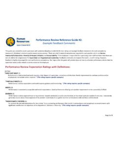
8 As the term indicates, underpinning is a procedure in which the foundation is physically reinforced. Underpinning should be conducted only under the direction and with the approval of a registered professional engineer Shielding Types Trench Boxes Are different from SHORING because, instead of SHORING up or otherwise supporting the trench face, they are intended primarily to protect workers from cave-ins and similar incidents. The excavated area between the outside of the trench box and the face of the trench should be as small as possible. The space between the trench boxes and the excavation side are backfilled to prevent lateral movement of the box. Shields may not be subjected to loads exceeding those which the system was designed to withstand. TRENCH SHIELD. TRENCH SHIELD, STACKED. Combined Use Trench boxes are generally used in open areas, but they also may be used in combination with sloping and benching.
9 The box should extend at least 18 in ( m) above the surrounding area if there is sloping toward excavation. This can be accomplished by providing a benched area adjacent to the box. Earth excavation to a depth of 2 ft ( m) below the shield is permitted, but only if the shield is designed to resist the forces calculated for the full depth of the trench and there are no indications while the trench is open of possible loss of soil from behind or below the bottom of the support system. Conditions of this type require observation on the effects of bulging, 4 | P a g e heaving, and boiling as well as surcharging, vibration, adjacent structures, etc., on excavating below the bottom of a shield. Careful visual inspection of the conditions mentioned above is the primary and most prudent approach to hazard identification and control.
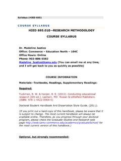
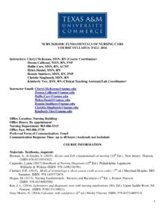
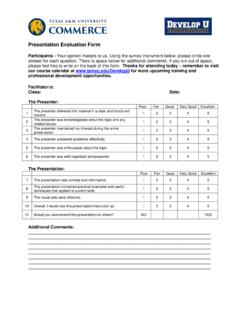
10 Slope and Shield Configurations. Sloping and Benching Sloping Maximum allowable slopes for excavations less than 20 ft ( m) based on soil type and angle to the horizontal are as follows: ALLOWABLE SLOPES. Soil type Height/Depth ratio Slope angle Stable Rock Vertical 90 Type A :1 53 Type B 1:1 45 Type C 1 :1 34 Type A (short-term) :1 63 (For a maximum excavation depth of 12 ft) 5 | P a g e Slope Configurations Excavations In Layered Soils Excavations Made In Type A Soil Benching There are two basic types of benching, simple and multiple. The type of soil determines the horizontal to vertical ratio of the benched side. As a general rule, the bottom vertical height of the trench must not exceed 4 ft ( m) for the first bench. Subsequent benches may be up to a maximum of 5 ft ( m) vertical in Type A soil and 4 ft ( m) in Type B soil to a total trench depth of 20 ft ( m).