Transcription of Tribology Issues in Electrical Contacts
1 Tribology Issues inElectrical BryantMechanical EngineeringThe University of Texas at AustinAustin, Texas 78712-1063 Dedicated to the late Dr. Ralph Ashley Burton,who introduced me to Electrical IntroductionDefine Electrical contactsReview: contact principlesReview: Electrical concepts Electrical contact physics Selected problem areasConnectorsSliding Contacts /brushesSwitches and relaysElectrical Contacts Review Definition:Ragnar Holm, Electric Contacts , Theory andApplication, 4th edition, Springer-Verlag, NewYork, contact .. a releasable junctionbetween two conductors which is apt to carryelectric current.
2 Purpose: Transfer charge across a mechanicalinterface between conductors. Electric contactspermit frequent and convenient connection anddisconnection of circuits. Common ApplicationsSwitches & RelaysConnectors & PlugsSliding Contacts : brushes Background = All areas of classical physics: Tribology + Electrical Engineering + Chemistry +Materials + Mechanics + Quantum effectsElectrical contact MakePress bodies together contact pressures & areaVoltage difference currentCharge carriers jump interfacial gapContact impedance ( resistance ) depends onReal contact areamaterialsfilmsconductor 1conductor 2lines of currentElectrical ContactRequirements ElectricalConductiveNegligible effect oncircuit: small impedanceStable.
3 No impedancefluctuations MechanicalContact stays togetherCompact Chemically & thermallystable Cost effectiveconductor 1conductor 2lines of current1 contact PrinciplesHERTZIAN THEORY2aPPZf(x, y)xp(x,y) p(x, y) = poa2 - x2 - y2 po = 3P2 a2 a = {3 P(k1+k2)R1R24(R1+R2) }13 ki = 1- i2 Ei ={9 2P2(k1+k2)2(R1+R2)16R1R2 }13 2 PLASTIC contact THEORY Indentation (Meyer) hardnessPPBodies in contact APPpLoad P > elastic limit plastic deformations contact pressures p(x, y) approximately uniform Hardness pressure (indentation hardness) p P A H 3 x Yield stress Use: estimate contact area, given H and P3 OVERALL contact MODEL2aPPp(x,y)PP 2 1 Spheres Increasing normal load P0 P < Pe ;Elastic (Hertzian) contact model = 1+ 2 = {9 2P2(k1+k2)2(R1+R2)16R1R2 }13 P Pe.
4 Plastic contact model = 1+ 2 > {9 2Pe2(k1+k2)2(R1+R2)16R1R2 }13 Similar formulations, tangential loads & deformations4 Electrical ConceptsElectric field: force per charge [N C 1 = V m-1]Voltage: energy per charge [volt V = J C-1]Current: charges in motion [ampere A = C s-1] requires charge [coulomb C] carriersElectrons: e-Holes: p+ Conduction mechanismsFree electrons e- in metalsBarrier gap/work function potential gape- jumps gap if sufficient kinetic energyV < gap suggests no currentTunnel effect: distribution of energies overpopulation of charge carriers, some have enoughkinetic to jumpdistanceenergyperchargeelectrode 1electrode 2 gapVgapkinetic energy distributionV gapkinetic energy: e-5 Current density: [A m-2]Impedance: Z = V/I, resistance to current flowZ = R + j X resistance : R = l/A [ohm = V A-1]Resistivity: [ m]Area: A [m2]Length: l [m] Reactance: X fromInductance L [henry H = s]ZL = j LCapacitance C [farad F = C V-1 = -1 s]ZC = 1/j C6 Constriction resistance Lines of current constrict near contact Water draining from bathtub.
5 Constriction impedesflow Generates resistanceR = dr/A(r) = /(2 r2 ) dr /2 (1/a 1/r ) : bulk resistivity of body; a: contact radius Neglects volume r < a Actual Constriction resistance : Rc = /2a contact radius a via mechanical contactr + drr2a7 Surface Films Thin films: nm to m Thickness dependentresistivity: f = f(s) Film formed viacontaminant diffusion& corrosion Mechanical Effects offilm negligible Film ResistanceRf = f/A ds Tunnel effect candominate f & Rfbody 1body 2film8 Continental Analogy of contact Rough surfaces:earth & Electrical contactsNorth AmericaSouth AmericaAndesMountainsAppalachianMountain sRockyMountainsBrazilHighlands Invert South America,place atop NorthAmerica contact .
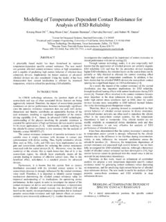
6 Highest peaksagainst highest peaksAndes/AppalachiaHighlands/Rockies Small, discrete contact areas at highest peaks14 Analogous to bodies in contactRough surfacesSmall, discrete contact areas (a-spots) parallel circuits & micro-constrictions Pores in contact allows easy contaminant diffusioncontact area withmicro-contactsa-spotglobal constrictionroughsurfaces15 contact Impedance Zc = Rc1 + j Lc1 + 1/( Rm 1 ) + 1/ ( 1/Rf + j C)+ Rc2 + j Lc2 + 1/( Rm 1 ) Rc = Rc1 + 1/( Rm 1 ) + Rf + Rc2 + 1/( Rm 1 ) Inductance & capacitance effects small @ lowfrequency RcRfCfglobalconstrictionsurface filmeffectsrough contactmicro-constrictionslines of current16 Joule Heating contact resistance dissipates power: P = i2 Rc Heat sources Field equationsElectrical: J = [1 e(T) V] = 0 (Laplace) thermal : [k(T) ]+ q = Cp(T) T t (Fourier) q = qe = J E = 1 e V V210012z/ Equipotential contours and isotherms for electricalheating of carbon graphite with a cold contactboundary with a = 1 mm.
7 Applied voltage: 2 EffectsDC voltageBodies become anode and cathodeAffectsChemistryMaterial behaviorArcingExamplesCathode brush wear > anode brush wearGraphite sticks to cathodeSelective film formation on anode/cathodeAffects contact resistanceAnode/cathode arc erosion different18 Switches & RelaysFunction, design, & purpose: frequent and rapidopening & closing of circuits. Often contains twometallic contactor / Relays / Reed SwitchesPictures: Eaton website ( )19 Arcing Existing contact with current flow contact break interrupts circuit Circuit inductance L opposes current change viainduced voltage VL = L di/dt Analogy: mass induces inertial force FI = m dv/dt Charge carriers needed for current to jump gap Air molecules ionize under voltage VL = VL(t) Plasma formed: fourth state of matter Arc = Current through ionized column closed contactopen circuit:inductancesinduce air ionsarc currentflows viaions from air20 Destructive.
8 Melts, welds & erodes electrodesMaterial transfer: anode - cathodeSegregation & recrystallizationSurface rougheningPhoto: C. H. Leung & A. Lee, 1993, Silver Tin Oxide contact Erosion inAutomotive Relays, Proc. 39th IEEE Holm Conference, pp. 61-6721 Elevated & sporadic contact resistanceChart: Z. Chen & K. Sawa, 1994, Polarity Effect of Unsymmetrical MaterialCombination on the Arc Erosion and contact resistance Behaviour, Proc. 40thIEEE Holm Conference, pp. 79-88. Always present in switches, relays, plugs, etc. Often: arc travels along cathode, stationery onanode_22 Research Issues /Design Problems Arc suppression Guide arc path Control contact bounce: repeated arcing Materials selection: powderedCu-CrNi-CdOAg-CdOAg-SnO2Ag-SnO2I n2O3Ag-MeO23 Connectors Function, design, & purpose: permanent but quickconnections/disconnects5-40 year stable life Connector classespower connectors: power lines & junction boxesautomotiveelectronic connectors: low power & compactTelephoneselectronicscomputers24 Power connectors.
9 Aluminium Lightweight Economic Conductive Form passivating films Problem:stress relaxation @ higher temperaturesloss of contact area higher Rcrisk: firesExamples: wire nuts, wedge connectors, clampsPhoto: J. J Schindler, Axon & Timsit, 1995, Mechanical andElectrical contact Properties of Wedge Connectors, Proc. 41st IEEE HolmConference, pp. Connectors Low power: contamination problemsdustpollutantscorrosive agents fretting corrosion IBM, late 1980s: connector problems cause 50% ofall computer failuresPictures: Molex website ( )26 Fretting Corrosionfretting time (cycles)100102104106 contact resistance (m )110100 SurfacefilmsbrokenStableIncreasewithfluc tuationsDrasticIncreaseStage 1 Stage 2 Stage 3 Elevated & fluctuating contact resistance Elevated resistance : digital high low,computer failure Fluctuations noise to signals27 Fretting Mechanism virginasperities mth cycle.
10 Motions expose a-spotscorrosive layers formh 1to 100 nmmAex posed(m ) Micro-motions @ contactStray vibrationsThermal expansions via temperature variation Normal & tangential motions Surfaces exposed: corrode Surface wear: corrosion & metal Buildup of fretting debris Surfaces separated, resistance changes28 Connector Issues Connector Insertion Force: Springs relaxation Healing mechanisms: breaking/penetrating films contact force: fractures Wipe: fractures & displaces Fritting: Joule heat from small filaments throughfilm softens/melts metal; plastic deformationsbrings electrodes closer & breaks film.