Transcription of Troubleshooting Guide - iN•Command
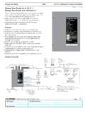
1 Troubleshooting Guide RV-C System Layout BCM Pin Values Pin Name BCM Function Note A DMM Tanks 1 Fresh 1 Tank In Input from Sending Unit = EMPTY ( ) . = 1/3 ( ) = 2/3 ( ) = FULL ( ) MEASURE FROM PIN 11 TO EACH INPUT VDC 2 Fresh 2 Tank In Input from Sending Unit VDC 3 Black 1 Tank In Input from Sending Unit VDC 4 Black 2 Tank In Input from Sending Unit VDC 5 Gray 1 Tank In Input from Sending Unit VDC 6 Gray 2 Tank In Input from Sending Unit VDC 7 Gray 3 Tank In Input from Sending Unit VDC 8 Tank Common 7 VDC Output to all Tanks 7 VDC Interior Lighting I/O 9 Light Group 1 12V Switch IN Input From External momentary Switch 15A 12 VDC 10 Light Group 1 12V 15A IN Input From Main Breaker Box 12 VDC 11 Light Group 1 Ground Common Ground GND
2 12 Light Group 1 12V 15A Out Output 12 VDC to LG 1 12 VDC 13 Light Group 2 12V Switch In Input From External momentary Switch 12 VDC 14 Light Group 2 12V 15A In Input From Main Breaker Box 12 VDC 15 Light Group 2 Ground Common Ground GND 16 Light Group 2 12V 15A Out Output 12 VDC to LG 2 12 VDC 17 Light Group 3 12V Switch In Input From external momentary Switch 12 VDC 18 Light Group 3 12V 15A In Input From Main Breaker Box 12 VDC 19 Light Group 3 Ground Common Ground GND 20 Light Group 3 12V 15A Out Output 12V to LG 3 12 VDC 21 Light Group 4 12V Switch In Input From External momentary Switch 12 VDC 22 Light Group 4 12V 15A In Input From Main Breaker Box 12 VDC 23 Light Group 4 Ground Common Ground GND 24 Light Group 4 12V 15A Out Output to LG 4 12 VDC Exterior Lighting I/O 25 Exterior Light 12V Switch In Input From External momentary Switch 12 VDC 26 Exterior Light 12V 15A In Input From Main Breaker Box 12 VDC 27 Exterior Light Ground Common Ground GND 28 Exterior Light 12V 15A Out Output 12V to Exterior Light 12 VDC BCM Pin Values (Cont.)
3 Pin Name BCM Function Note A DMM Security Light I/O 29 Security Light 12V Switch In Input From External momentary Switch 12 VDC 30 Security Light 12V 15A IN Input From Main Breaker Box 12 VDC 31 Security Light Ground Common Ground GND 32 Security Light 12V 15A Out Output 12V to Security Light 12 VDC Fuel Station 33 Fuel Station Tank Level In Input from Sending Unit 33 OHM= FULL ( ), 49 OHM= 2/3 ( ) 127 OHM= 1/3 ( ), 240 OHM= Empty ( ) 34 Fuel Station GND GND Pass Through Connection GND Generator 35 Generator Start Ground Out Output Ground until button is released GND 36 Generator Prime/Stop Ground Out Output Ground GND 37 Generator Service 12V In 12V Pulse Input 12 VDC 38 Generator Hour Meter 12V In 12V Input triggers timer to start 12 VDC 39 Generator Fuel Level In Input from Sending Unit 33 OHM= FULL ( ), 49 OHM= 2/3 ( ) 127 OHM= 1/3 ( ), 240 OHM= Empty ( ) 40 Generator Ground Common Ground GND HYD Landing Gear 41 +12V Hydraulic Valve (Landing Gear)
4 Output 12V 12 VDC 42 Ground Hydraulic Valve (Landing Gear) Common Ground GND 43 Hydraulic Extend Out 12V 2A Output 12V for Extend Valve 2A GND 44 Hydraulic Retract Out 12V 2A Output 12V for Retract Valve 2A GND BCM Pin Values (Cont.) Pin Name BCM Function Note A DMM HYD Slides 45 12V Hydraulic Valve (Slide Solenoid) Output 12V 12 VDC 46 Ground Hydraulic Valve (Slide Solenoid) Common Ground GND 47 No Connection 48 No Connection AUX Triggers 49 Trigger 1 12V Out Programmable 12V Latch or momentary 1A 12 VDC 50 Trigger 2 12V Out Programmable 12V Latch or momentary 12 VDC 51 Trigger 3 12V Out Programmable 12V Latch or momentary 12 VDC 52 Trigger 4 12V Out Programmable 12V Latch or momentary 12 VDC Alarm Inputs 53 Alarm 1 12V In Programmable 12V On or Off Input 1A 12 VDC 54 Alarm 2 12V In Programmable 12V On or Off Input 12 VDC 55 Alarm 3 12V In Programmable 12V On or Off Input 12 VDC 56 Alarm 4 12V In Programmable 12V On or Off Input 12 VDC Travel Lockout 57 Travel Lockout 12V In 12V Input from Tow Vehicle Brake signal Locks
5 Out all motor functions when signal is present 12 VDC Water Heater 58 Water Heater Ground Common Ground GND 59 Water Heater Gas 12V 1A Out 12V Output to Gas Ignitor 1A 12 VDC 60 Water Heater Electric 12V 1A Out 12V Output to Electric Ignitor 12 VDC 61 Water Heater 12V Fault In Receive 12V Fault Signal 12 VDC BCM Pin Values (Cont.) Pin Name BCM Function Note A DMM Awning Light 62 Awning Light 12V Switch In Input From External momentary Switch 12 VDC 63 Awning Light 12V 3A Out Output 12V to Awning Light Power from Awning 15A Input 3A 12 VDC 64 Awning Light Ground Common Ground GND Water Pump 65 Water Pump 12V 10A Out Output 12V to Water Pump 10A 12 VDC 66 Water Pump Ground Common Ground GND 67 Water Pump 12V 15A In Input From Main Breaker Box 10A 12 VDC Awning Motors 68 Awning 2 Retract Out Output Reversing Polarity DC Motor 15A 12V/GND 69 Awning 2 Extend Out Output Reversing Polarity DC Motor 12V/GND 70 Awning 1 Retract Out Output Reversing Polarity DC Motor 12V/GND 71 Awning 1 Extend Out
6 Output Reversing Polarity DC Motor 12V/GND Jacks 72 Rear Jack Retract Out Output Reversing Polarity DC Motor 30A 12V/GND 73 Rear Jack Extend Out Output Reversing Polarity DC Motor 12V/GND 74 Front Jack Retract Out Output Reversing Polarity DC Motor 12V/GND 75 Front Jack Extend Out Output Reversing Polarity DC Motor 12V/GND Electric Slide Motors 76 Slide 5 Retract Out Output Reversing Polarity DC Motor 12V/GND 77 Slide 5 Extend Out Output Reversing Polarity DC Motor 12V/GND 78 Slide 4 Retract Out Output Reversing Polarity DC Motor 12V/GND 79 Slide 4 Extend Out Output Reversing Polarity DC Motor 12V/GND 80 Slide 3 Retract Out Output Reversing Polarity DC Motor 12V/GND 81 Slide 3 Extend Out Output Reversing Polarity DC Motor 12V/GND 82 Slide 2 Retract Out Output Reversing Polarity DC Motor 12V/GND 83 Slide 2 Extend Out Output Reversing Polarity DC Motor 12V/GND 84 Slide 1 Retract Out Output Reversing Polarity DC Motor 12V/GND 85 Slide 1 Extend Out Output Reversing Polarity DC Motor 12V/GND Power 86 Ground In Input From Chassis Ground GND 87 Power Chassis 12V In Input From Chassis Battery (Motorized)
7 12 VDC 88 Awning Power 12V 15A In Input From Main Breaker Box 15A 12 VDC 89 Electric Slide/Jack Power 12V 30A IN Input From 12V 30A mini reset fuse 30A 12 VDC 90 Main Power 12V 15A In Input From Main Breaker Box 15A 12 VDC NCSP3 Functionality Test The Body Control Module (BCM) should be wired correctly, without loose connections, and connected to 12 VDC at pin 90. A RED LED will indicate that the BCM is receiving 12 VDC. The 2 toggle switches on the BCM correspond to the 2 dials underneath them. (In the event where communication between the Display Commander (DC) and BCM is non-functioning, these switches will enable "manual" functions of the selected devices) The Left switch and knob are used for Electric Awnings and Jacks.
8 (Hydraulic Jacks are manually controlled at the Hydraulic Pump. See the Hydraulic Pump Manual Override in the RV owner's manual), and the Right switch and knob are used for Electric Slides 1 - 5. The BCM and DC communicate with each other through an RV-C (CAN BUS) connection. This RV-C communication also allows the DC to connect to a third party AC translator module (gateway) so that you can perform the HVAC functions from the DC. The Display Commander (DC) will be mounted in an "all access" area near the entrance. On the DC, press and release the Power button (the left button) to wake up the DC. After a moment, the Passcode Screen will appear. Enter your Passcode. If this is the first time the DC has been powered on, an End User License Agreement (EULA) screen will appear.
9 Upon accepting the EULA, an Enter New Passcode screen will appear. Enter your new passcode and confirm. The DC will now bring up the Home Screen If the Floor Plan has been loaded, all of the devices should be listed with corresponding actitation buttons Go through all the functions and make sure they are operating properly. All the functions should be smooth and instantaneous. Ensure all the Home Page Hot keys actuate/turn on the corresponding functions. Cycle the Generator. When the Generator is being cycled for the first time (or if it has been a while since it has been used), it will need to be primed. Hold the Prime button down to 2 -5 seconds, then press and hold the Start button down until the generator starts.
10 IN-Command is also equipped with an Auto Gen start. Press the Manual button to switch to Auto to activate the Auto Gen start function. If the battery voltage is less than for 3 minutes, the system will start the generator. If the generator is started, the generator will run for 60 Minutes. Also, the system will attempt to start the generator 3 times. If the generator fails to start after the 3rd attempt, the system will turn off the Auto feature and display a Check Generator Fault Message. HVAC Testing When testing the HVAC (Climate Function), make sure each Zone is displaying a room (Zone) temperature. Use the Mode button to cycle through Fan, Cool, Heat and Auto modes.