Transcription of True-Fire Electronic Ignition System Installation 6, …
1 1 Bittner Engineering, LLC 87 Mungertown Road Madison, Ct 06443 (203)245-4669 True-Fire Electronic Ignition System Installation 6, 8 or 12 Volt Operation Revised February 20, 2004 Introduction: Congratulations on your purchase of the Bittner Engineering True-Fire Ignition System . This Ignition System is designed to operate on any voltage between 6 and 12 VDC and replaces the original commutator and coils on your Model T Ford. It will give much more reliable Ignition results than the original System (no moving parts). The best part is, your Model T will look and operate exactly like it did when Henry made it.
2 Your timer and timer wiring harness remain the same and the spark plug wires remain the same - connected to your original coil box. Each True-Fire Ignition System is thoroughly tested and functioning properly prior to shipment. It should be noted that, although the True-Fire performance will be superior to the original System , it is not a cure-all for other problems that may cause poor engine performance such as a bad coil box, poor wiring, bad valves or a poorly functioning carburetor. Your True-Fire Electronic Ignition kit should include the following components: 1 - Coil Box Module 1 Rotor 1 - Ground Wire 1 - Timer Module 1 - Split Lock Washer 1 - Instruction Pages Tools required for the Installation of your True-Fire Ignition System : 9/16 Open End Wrench 3/8" Open End Wrench 300 600 Grit Sandpaper 3/4 Open End Wrench Ohmmeter Before you begin installing your new Ignition System please read the entire Installation procedure.
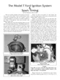
3 Pay close attention to all precautions outlined. 1. Disconnect your battery. Make sure your car has a negative ground System . A positive ground System will damage the True-Fire Electronic Ignition System . Model T's were made with a negative ground System but some owners have changed them through the years. Many people think they have a negative ground System until they check it. 2. Loosen the timer spring arm and remove the timer (commutator). Remove the timer control rod (only at timer side). Disconnect the wires from the timer. 3. Remove the nut from the end of the cam shaft, the retainer cup, pin, and roller.
4 If your engine has a shield holding the felt in place, remove it. The new rotor will hold the felt in place. We suggest the Installation of a modern camshaft seal which works much better than the original felt seal. 4. Clean the timing gear cover. If you are going to use your existing timer, clean your timer thoroughly, removing all oil, grease and grit. Be sure to clean deep behind the contacts on the timer. If you are using a new timer, you may want to clean your old timer and retain it as a backup. 5. After checking the camshaft for burrs, slip the plastic rotor onto the cam shaft aligning the slot on the rotor with the hole in the cam.
5 If your cam has a hole on both sides, it makes no difference which one you use. Place the pin through the rotor slot and cam hole and install the retainer cup over the pin. Slide the supplied split lock washer over the end of the cam. Screw the cam nut on the cam just until the lock washer is compressed. Do not compress/distort the plastic rotor. 2 6. Loosen and remove the nuts and insulators on the four wire terminals located on the outside of the vintage timer. Carefully remove the four terminals by taping them toward the inside of the timer and place them aside. The insulator washers and nuts will be used in step #8.
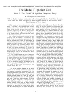
6 Important: The small hole on the module should be at the top of the timer on 1909 - 1925 cars with coil boxes on the firewall and should be at the bottom of the timer on 1926 - 1927 cars whose coil box is mounted on the engine. (On right hand drive cars the small hole in the plastic module hole will still be at the top on early cars and at the bottom on '26-'27 cars, but the spark rod lever is on the bottom of the timer instead of the top.) 7. After determining the correct position of the plastic timer module, push the supplied 10-32 brass screws through each of the four holes in the module from the inside out, making sure they go through the wire loops on the circuit board.
7 8. Make sure the 10-32 brass screws do not contact the steel timer housing. Place the plastic insulators over the brass screws and screw the nuts down until they are snug. Carefully tighten the four nuts making sure the plastic timer module is centered on the timer. Do not over tighten the nuts. After driving the car about 100 miles, it may be necessary to retighten all the nuts because the plastic seems to "relax" slightly. 9. After installing the plastic module in the timer, connect the wiring harness to to the appropriate terminals on the timer. It is a good idea to check to make sure you have continuity between each of the corresponding timer connections and the appropriate terminals on the coil box (see reference illustration); they should be wired according to the applicable original Model T diagram on the following page.
8 Reinstall the timer over the front of your camshaft and re-attach the timer control rod. The timer should rotate freely on the timing gear cover plate when using the spark lever on the steering column. If not, investigate and correct the cause of the problem. Important: Do not allow any of the screw terminals on the timer to touch any part of the engine. On 1909-1925 cars the #1 & 2 terminals trigger the coil. The #3 terminal is battery positive for the timer only and the #4 terminal is ground. If the #3 terminal touches ground you may damage the unit. Check to make sure the screw terminals clear all grounding sources through the full rotational motion as the spark lever is moved from full up to full down.
9 On 1926-1927 cars the #3 & 4 terminals trigger the coil. The #2 terminal is battery positive for the timer only and the #1 terminal is ground. If the #2 terminal touches ground you may damage the unit. Check to make sure the screw terminals clear all grounding sources through the full rotational motion as the spark lever is moved from full up to full down. 10. Remove all four of the vintage coils from the coil box. If your coil box has a metal brace across the center, remove the brace. Inspect to make sure that the coil box is in good condition. The wood should be clean and sealed with polyurethane or an equivalent treatment to make sure water and moisture will not penetrate it, consequently shorting out the System .
10 The spring metal contacts should be very clean and not compressed. The spring contacts come in right-hand and left-hand sets; make sure they are facing the correct direction in your box. The bolts clamping the contacts and insulators should be solid brass, solid copper, or copper plated. Copper plated bolts that have been grit blasted or have damaged plating are poor conductors and could cause misfiring problems. All of the hardware should be tight and secure. After checking and adjusting the coil box, install the True-Fire "Super Coil" Module. It will seem to fit tighter than the vintage this is normal and is expected because all of the contacts are engaging at the same time.