Transcription of TrueAlarm Smoke Detectors - Simplex Home
1 Features Compact air duct detector housing with clear cover to monitor for the presence of Smoke ** Includes factory installed TrueAlarm photoelectric Smoke detector and features: On-board TrueAlarm sensitivity drift compensation and dirt accumulation tracking Multi-function status LED indicator Magnetic test that initiates an alarm and provides detailed diagnostic information Clear cover allowing visual inspection Test ports provide functional Smoke testing access with cover in place UL listed to Standard 268A Model availability: 4098-9685, 2-Wire standard operation 4098-9688, 2-Wire with supervised control for a single remote relay (relay included) 4098-9686, 4-Wire operation with supervised control for multiple remote relays (includes one remote relay) Mounts to rectangular ducts or round ducts Minimum size is 8 (203 mm) square or 18 (457 mm) diameter Magnetically operated functional test: Initiates alarm and displays dirt accumulation status using the detector status LED Assists with maintenance priorities by categorizing detector status and identifying dirty Detectors Sampling tubes (ordered separately): Available in multiple lengths to match duct size Installed and serviced with housing in place Remote module options (ordered separately).
2 Red alarm LED (4098-9830) Test stations with LED(s) and keyswitch (refer to page 2 for compatibility) Relays for remote control applications * These products have been approved by the California State Fire Marshal (CSFM) pursuant to Section of the California Health and Safety Code. See CSFM Listing for allowable values and/or conditions concerning material presented in this document. Accepted for use City of New York Department of Buildings MEA35-93E. Additional listings may be applicable; contact your local Simplex product supplier for the latest status. Listings and approvals under Simplex Time Recorder Co. are the property of Tyco Fire Protection Products. ** Please note that Smoke detection in air ducts is intended to provide notification of the presence of Smoke in the duct. It is not intended to, and will not, replace Smoke detection requirements for open areas or other non-duct applications.
3 This device is a duct Smoke housing. When provided with detector, it is designed to sample the air flowpassing by it in the air duct to determine whether it contains unacceptable levels of Smoke . Theeffectiveness of a duct Smoke detector is highly dependent upon: the design and operating conditions of theair handling system in which it is installed, variables such as Smoke dilution and stratification over whicheven the best designed systems have no control, and proper placement and positioning of the duct smokedetector, which is often compromised for practical reasons. For the reasons stated above, the effectivenessof this duct Smoke detector cannot be warranted or guaranteed. Under no circumstances should this ductsmoke detector be used or regarded to be a substitute for the building's Fire alarm and detection system towhich this device is attached as a secondary detection NOT REMOVE THIS NOTICE!
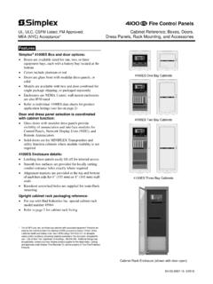
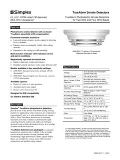
4 Duct Detector Housing, Front and Bottom View ALARM TESTNORMALARM TESTNORMPOWERALARM 4098-9830 4098-9834 4098-9835 Remote Alarm Indicators and Test Stations Introduction Operation. Simplex air duct Smoke detector housings provide a TrueAlarm Smoke detector for monitoring air conditioning or ventilating ducts. Sampling tubes are installed into the duct allowing air to be directed to the Smoke detector mounted in the housing. These duct detector housings with Smoke Detectors are compatible with Simplex fire alarm control panels that provide conventional two-wire or four-wire initiating device circuits (IDCs). Model Details Each supports a remote red alarm LED or a remote test station with LED(s). Models with relay output provide relay coil wiring supervision that will transfer a trouble to the IDC if supervision is lost. 2-Wire Model 4098-9685 provides basic Smoke detection for applications that do not require a remote relay.
5 Power is from the IDC. 2-Wire Model 4098-9688 provides a supervised relay output for connection to a single 4098-9841 relay. This model is powered from the IDC and requires connection as the only device to ensure relay operation. 4-Wire Model 4098-9686 provides a supervised relay control output that can control up to 15, 4098-9843 control relays. Relay supervision troubles are indicated by a yellow LED on the interface board. (Resettable 24 VDC is required, see page 4.) Remote test station 4098-9835 is available for use with this model to provide a test keyswitch, a red LED alarm indicator and a green power-on LED. TrueAlarm Smoke Detectors UL, ULC, CSFM Listed; FM Approved, Duct Detector Housings with TrueAlarm Photoelectric MEA (NYC) Acceptance* Detector for 2-Wire or 4-Wire Operation S4098-0029-9 11/2014 2 S4098-0029-9 11/2014 Duct Smoke Detector Housing with Photoelectric Detector* Model Description Compatibility 4098-9685 2-Wire Duct Detector, standard operation No relay(s) Remote LED indicator and test stations per below 4098-9688 2-Wire Duct Detector with supervised single remote relay output; includes one 4098-9841 relay; NOTE: Must be only device on IDC for proper relay operation; (When used with the Simplex 4004 or 4005 fire alarm control panel, connect to high current IDCs only) Supplied relay is required for proper operation 4098-9686 4-Wire Duct Detector with supervised multiple remote relay output.
6 Requires resettable 24 VDC fire alarm power and relay end-of-line resistor 4081-9008; includes one 4098-9843 relay Up to 15 total 4098-9843 relays (additional relays are ordered separately) LED Indicator and Remote Test Stations (Select one if required) Each assembly is on a single gang stainless steel plate, wiring is 18 AWG ( mm2 ) color coded wire leads Model Description Compatibility Mounting 4098-9830 Red LED alarm indicator 4098-9685 4098-9688 4098-9686 Use single gang box, 3 H x 2 W x 2 D (76 mm x 51 mm x 51 mm) 4098-9834 Test Station with keyswitch and red LED alarm indicator (turning switch to TEST initiates alarm for system testing) 4098-9835 Test Station with keyswitch, red LED alarm indicator, and green power-on LED 4098-9686 only Epoxy Encapsulated Remote Relays and End-of-Line Resistor (wiring is 18 AWG ( mm2 ) color coded wire leads)
7 Model Description Compatibility Mounting 4098-9841 Relay, dual Form C (1/2 A @ 120 VAC); included with 4098-9688 Refer to pages 3 and 4 for additional relay information 4098-9688 only, one maximum Locate relays within 3 ft (1 m) of device being controlled, per NFPA 72 4098-9843 Relay, single Form C (7 A @ 120 VAC); one included with 4098-9686 4098-9686 only, connect up to 15 4081-9008 End-of-Line Resistor Harness; 10 k , 1/2 W; (ref. 733-894); required to supervise remote relay coil connection 4098-9686 At last relay location * Each duct housing includes an internally mounted model 4098-9601 TrueAlarm photoelectric detector and an exhaust tube. A correctly sized sampling tube (ordered per application) is required, refer to chart below. LED Indication Status Pulses approximately every 4 seconds Normal Steady On Alarm Detector LED Response to Magnetic Test ** LED Indication Followed By Status Action LED turns ON Alarm is initiated Normal, sensitivity is within compensation range None LED pulses quickly, 6 times in 3 seconds, then turns ON Alarm is initiated More sensitive, out of normal compensation range Cleaning or other service is required LED pulses slowly, 4 times in 8 seconds, then turns ON Alarm is initiated Less sensitive, out of normal compensation range Does not initiate Alarm Detector is malfunctioning Service is required ** Testing requires placing a magnet at the designated location on the duct housing cover for 4 seconds and referring to the response from the red LED status indicator on the detector.
8 Refer to Installation Instructions 574-776 for further test and maintenance information. Overall Duct Width Tube Required Suggested Cut Length 12 (305 mm) 4098-9854 1/2 ( mm) longer than duct width 13 to 23 (330 mm to 584 mm) 4098-9855 1/2 ( mm) longer than duct width 24 to 46 (610 mm to 1168 mm) 4098-9856 3 in (76 mm) longer than duct width 46 to 71 (1168 mm to 1803 mm) 4098-9857 3 in (76 mm) longer than duct width 71 to 95 (1803 mm to 2413 mm) 4098-9858 3 in (76 mm) longer than duct width Duct Detector Selection Chart Sampling Tube Selection Chart, Ordered Separately Per Duct Width, Select One TrueAlarm Detector Status LED Indications NOTE: Refer to Installation Instructions 574-776 for additional detail and maintenance information. This device is a duct Smoke housing. When provided with detector, it is designed to sample the air flow passing by it in the air duct to determine whether it contains unacceptable levels of Smoke .
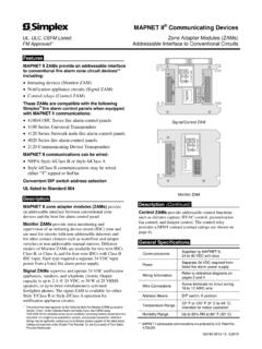
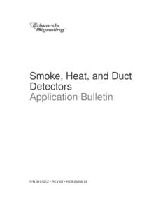
9 The effectiveness of a duct Smoke detector is highly dependent upon: the design and operating conditions of the air handling system in which it is installed, variables such as Smoke dilution and stratificationover which even the best designed systems have no control, and proper placement and positioning of the duct Smoke detector, which is often compromised for practical reasons. For the reasons stated above, the effectiveness of this duct Smoke detector cannot be warranted or guaranteed. Under no circumstances should this duct Smoke detector be used or regarded to be a substitute for the building's Fire alarm and detection system to which this device is attached as a secondary detection NOT REMOVE THIS NOTICE!6-3/4"(171 mm )11-3/8" (289 mm)Front ViewExhaust tube access holeSampling tube access holeCaptive fastening screws (4)Metal plate with dual holes for 3/4" (19 mm) conduit, plug supplied for unused hole Status LEDW iring terminalsMagnetic test areaConduit (by others)Stationary baffle (built-in)4098-9601 Smoke detector mounted in base (supplied)Yellow LED, relay control trouble indicator (4098-9686 only)Side of duct3-3/8"(86 mm)Gaskets (supplied)Test ports (2) provided for measuring airflow and for aerosol injection13/16" (21 mm)Sampling tube, ordered separately per duct widthExhaust tube (supplied)NOTE.
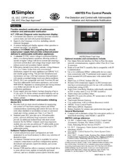
10 Orientation shown is for reference only, refer to General Location Notes and End View illustration below for alternate mounting coverGasketed detector areaDuct wallBottom viewSampling tube, keyed for proper hole alignment with holes facing into airflow(template is provided for proper tube installation). (Housing is shown as position 2 per note 2 below.)8" Square duct outline (minimum width)18" Round duct outline (minimum diameter)End View with Ducts and TubesGeneral Location Notes: 1. Testing performed under the auspices of the Fire Detection Institute (FDI) recommended when sampling tubes are not located vertically, that they be positioned horizontally in the upper half of the duct to account for possible Three duct side mounting options are available as shown housing at 90 to airflow for all orientations. Arrows indicate allowed airflow tubeDuct housingAlternate location (ifappropriate)Square duct reference outlineThis device is a duct Smoke housing.