Transcription of Truss Structures
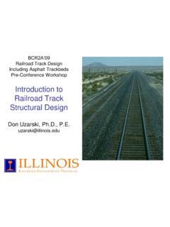
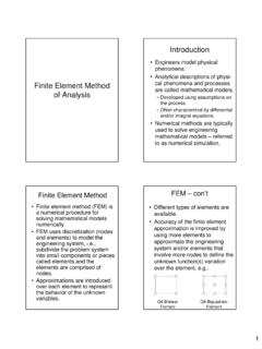
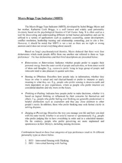
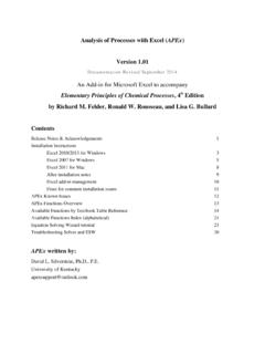
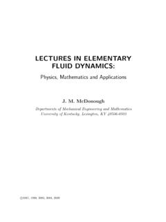
1 1 Truss StructuresTruss Definitions and Details2 Truss : Mimic Beam Behavior3 Bridge Truss Details4 Framing of a Roof Supported Truss5 Common Roof Trusses67 Buckling Calculations2weakcr2 EIP( L)buckling force ==keffective length factor1 for an ideal Truss member==kk8 Types of TrussesBasic Truss Element three member triangular trussSimple Trusses composed of basic Truss elementsm = 3 + 2(j -3) = 2j -3for a simple trussm total number of membersj total number of joints9 Simple Truss10 Compound Trusses constructed by connecting two or more simple trusses to form a single rigid body11 Complex Trusses Truss that is neither simple nor compound12 Analysis of TrussesThe analysis of trusses is usually based on the following simplifying assumptions: The centroidal axis of each member coincides with the line connecting the centers of the adjacent members and the members only carry axial force.
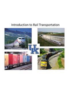
2 All members are connected only at their ends by frictionless hinges in plane trusses. All loads and support reactions are applied only at the reason for making these assumptions is to obtain an ideal Truss , , a Truss whose mem-bersare subjected only to axial Forces member axial forces determined from the analysis of an ideal trussSecondary Forces deviations from the idealized forces, , shear and bending forces in a Truss focus will be on primary forces. If large secondary forces are anticipated, the Truss should be analyzed as a of JointsMethod of Joints- the axial forces in the members of a statically determinate Truss are determined by considering the equilibrium of its (T) axial member forceis indicated on the joint by an arrow pulling away from the (C) axial member forceis indicated by an arrow pushing toward the Solution18 Zero Force Members:(a) If only two noncollinear members are connected to a joint that has no external loads or reactions applied to it, then the force in both members is zero.
3 (b) If three members, two of which are collinear, are connected to a joint that has no external loads or reactions applied to it, then the force in the member that is not collinear is Force Members 20 Figure (a):yABF0 Fcos= = ABF0 =xACABF0 FFsin==+ ACF0 =Figure (b):yACF0 Fcos= = ACF0 =0 Zero Member Force Calculations21 Truss analysis is easier if one can first visually iden-tify zero force members22 Method of SectionsThe method of sections enables one to determine forces in specific Truss members of Sections involves cutting the Truss into two portions (free body diagrams, FBD) by passing an imaginary section through the members whose forces are desired.
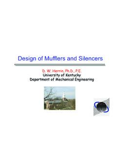
4 Desired member forces are determined by considering equilibrium of one of the two FBD of the of sectionscan be used to determine three unknown member forces per FBD since all three equilibrium equations can be of Sections Example24 BCHGHCF_____F_____F_____===25 Statics Principle of Transmissibility26 Transmissibility principle of staticsstates that a force can be applied at any point on its line of action without a change in the external effects27 BCGFF____F____==28 JCJFF____F____==29K- Truss Solution30 determinacy and StabilityInternal stability number and arrangement of members is such that the Truss does not change its shape when detached from the supports.
5 External Instability instability due to insufficient number or arrangement of external Stabilitym < 2j 3 Truss is internallyunstablem 2j 3 Truss is internally stable provided it is geometrically stablem total number of membersj total number of jointsGeometric stabilityin the second condition requires that the members be properly Determinate Truss if all the forces in all its mem-bers as well as all the external reactions can be determined by using the equations of Indeterminate Truss if all the forces in all its mem-bers as well as all the external reactions cannot be determined by using the equations of Indeterminacy excess number of support reactions33 Internal Indeterminacy excess number of membersRedundants excess members and reactionsNumber of redundants defines the degree of static indeterminacy ISummarym + R < 2j statically unstable trussm + R = 2j statically determinate trussm + R >2j statically indeterminate truss34 The first condition is always , the last two conditions are true if and only if the Truss is geometrically analysis of unstable trusses will always lead to inconsistent, indeterminate.
6 Or infinite determinacy Calculations36 Truss determinacy Calculations37 Equations of Condition: Plane Trusses