Transcription of TURBINE SUPERVISORY GUIDE - Vibration Monitoring, …
1 TURBINESUPERVISORYGUIDE25 YEARS1978 -2003 TECHNIQUES FOR THEMONITORING & PROTECTION OFPOWER PLANT EQUIPMENTTURBINESUPERVISORYGUIDEI ntroductionOverviewTSE Application DiagramTransducers and SensorsAccelerometerVe locity TransducerEddy Current Proximity ProbeLV DT/RVDTC hoosing the right transducerMeasurement TechniquesAbsolute VibrationEccentricity & Shaft VibrationRotor Differential ExpansionShaft PositionSpeed MonitoringCasing & Cylinder Expansion Valve Position MonitoringAuxiliary Plant MonitoringProtection SystemsIntroduction to API Standard 670 Special TechniquesRod Drop Rundown MonitoringOrbit AnalysisSystem EquipmentBracketryCubicle PanelsSeismic Monitoring andProtection EquipmentSite ReferencesQuick Product Selection GuideCONTENTS030411192024262718063 INTRODUCTIONFor nearly 30 years Sensonics has been supplyingTurbine Condition Monitoring solutions to thepower generation industry worldwide. Involved inmeasurement definition through to supply andfinal system commissioning, our experience withinthe power sector is second to have produced this GUIDE to capture theessence of that experience and to explain thebasics of Vibration and expansion measurementtechniques relating to TURBINE and auxiliary GUIDE starts with an introduction to the basictransducers available for plant mounting withassociated options, and details the variousmeasurement techniques used as standardthroughout the power industry.
2 This is followed bytypical equipment protection configurations forsafe plant shutdown. In the final part of this guidethe system components are introduced andspecial measurement regimes GUIDE aims to provide a balance of basictheory and practical advice but obviously cannotcover all measurement scenarios. For a detaileddiscussion on any measurement issues you mayhave, please feel free to contact & COMPETENCEST urbine SUPERVISORY SystemsStandalone Monitoring SolutionsAccelerometer, Displacement & Seismic TransducersNuclear Infrastructure ProtectionStructural Monitoring SolutionsTurn-Key Design, Manufacture and Project SupportATEX & IEC61508 CapabilityInstallation & Commissioning4 OVERVIEWT urbine supervision is an essential part of the day-to-dayrunning of any power plant. There are many potentialfaults such as cracked rotors and damaged shafts, whichresult from Vibration and this expansionand Vibration is apparent in its early stages the problemcan usually be resolved without any of the disruptioncaused when a TURBINE has to be shut down.
3 Byappropriate trending of the various measurement pointsand the identification of excessive Vibration ormovement, scheduled equipment stoppages or outagescan often be utilised to investigate and resolve the is for this predictive maintenance market that Sensonicsproduces a wide range of sensors and systems specificallyfor the power generation industry. With flexible andconfigurable equipment, we can tailor our supervisoryequipment to your needs. In this brochure we aim togive a brief explanation of why TURBINE supervision is soessential and how Sensonics can provide the rightsolution to protect your diagram on page 5 illustrates a generic configurationof a set of TURBINE SUPERVISORY equipment. The steamturbine shown is fairly standard with an HP (highpressure) stage followed by a single LP (low pressure)rotor section; different TURBINE configurations dependingon power rating, may have an intermediate (IP) section inaddition to a number of LP s which finally drive theturbine type of configuration is illustratedin the adjacent picture.
4 Although the equipmentconfiguration does vary, the measurement techniquesremain the same, with each TURBINE installation generatingits own unique set of measurements. Typicalmeasurement techniques include:-Absolute Vibration of bearing pedestalsShaft Vibration relative to bearingShaft eccentricityDifferential expansion or shaft movementValve position on steam inletCasing expansion, both inner and outerSpeed, including overspeed and zero speedTe mperatureStructural & foundation Vibration monitoringEach of the measurement techniques are used to monitorthe TURBINE during its operating cycle, somemeasurements may be configured to provide warningalarms as well as automated shutdown, although thesesystems tend to operate on a voted principle to ensuremaximum system TYPICAL TURBINE SUPERVISORY EQUIPMENT APPLICATION6 Shear mode devices which apply a shear force to theinner and outer surfaces of a ring of crystal (as opposedto a perpendicular force to a disk of crystal), offer adistinct advantage over standard compression mounting the device to the plant, normally througha stud & screw arrangement, the mechanical stresseswithin the transducer assembly change.
5 Compressionmode devices are particularly affected by these stresses,which produce low frequency effects, compounded iffurther integration is carried out. Sensonics shear moderange of transducers are unaffected by base strain andoffer a true low frequency performance down to the piezoelectric accelerometer is a self-generating device, its output is at a very high impedanceand is therefore unsuited for direct use with most display,analysis, or monitoring , electronics mustbe utilised to convert the high impedance crystal outputto a low impedance capable of driving such devices. Theimpedance conversion electronics may be located withinthe accelerometer, outside of but near the accelerometer,or in the monitoring or analysis device with internal electronics are convenientand can use inexpensive conventional plugs and cable butthey are limited to temperatures of typically 120 the electronics in a cool location away from theaccelerometer allows the transducer to tolerate & SENSORSThe AccelerometerThe accelerometer is based on the electrical propertiesof piezoelectric crystal.
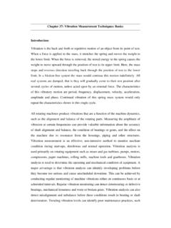
6 In operation, the crystal isstressed by the inertia of a mass. The variable forceexerted by the mass on the crystal produces an electricaloutput proportional to acceleration. Two commonmethods of constructing the device to generate a residualforce are compression mode and shear moderespectively. A residual force is of course required toenable the crystal to generate the appropriate response,moving in either direction on a single axis. A shear modeconstruction is illustrated accelerometer operates below its first naturalfrequency. The rapid rise in sensitivity approachingresonance is characteristic of an accelerometer, which isan un-damped single-degree-of-freedom spring masssystem. Generally speaking, the sensitivity of anaccelerometer and the ratio between its electrical outputand the input acceleration is acceptably constant toapproximately 1/5 to 1/3 of its natural frequency. For thisreason, natural frequencies above 30 KHz tend to be frequency response curve can be influenced by anumber of factors, mainly the mass, the stiffness and thedegree of system damping.
7 The resonant peak of theaccelerometer can be eliminated by increasing thedamping. However, increasing the damping introduces aphase shift in the linear range whereas un-dampedaccelerometers have very little phase shift until near thenatural frequency. It is therefore usual to have un-dampedaccelerometers with very high natural frequencies so thatthe linear range is extended as far as possible. Typicaldamping ratios are to resonant frequency in combination with theappropriate damping can be utilised to monitor bearingimpact. Several manufacturers, including Sensonics havedeveloped transducers that utilise the ringing of thetransducer to mechanical impulses to measure the healthof roller bearings. This technique analyses the highfrequency response of the transducer (at resonance) todetermine an impact factor normally in dB, which isdirectly proportional to the quantity and force of metalon metal factor is normalised to an overallhealth measurement by consideration of bearingdimensions and rotational mode constructionTypical accelerometer frequency response7 Accelerometers are available in various outputconfigurations.
8 The industry standard drive utilises a 2-wire current source interface operating at a nominal biasvoltage of +12 Vdc typ., with an output sensitivity of100mV/g. This configuration limits the dynamic range toaround 70g, which is suitable for most dynamic ranges can be achieved through loweringthe sensitivity at the expense of signal to noise ratio,10mV/g as an example, or utilising current output devices,which can provide 1000g depending on sensitivityrequirements (10pC/g is typical).Standard accelerometers are also available with velocityoutputs in either metric or imperial format, although forthese configurations the required measurement rangemust be understood if the correct sensitivity is to beselected (0-20mm/s, 0-50mm/s etc.). Since the integrationfunction to convert the acceleration to velocity is carriedout within the accelerometer, the low frequencyperformance is typically limited to around a few limited complexity of the conditioning circuitry thatcan be included within the accelerometer combined withthe integrated noise tend to be the limiting direct integration with SCADA and PLC basedsystems, most manufacturers offer direct 4-20mA outputscovering a factory set range of either acceleration orvelocity Vibration .
9 This can be an extremely cost effectivesolution (provided the required measurement range isagain well understood) since no signal conditioning unit isrequired to drive the transducer or process the resultingmeasurement. The resulting current loop output istypically either a peak or an RMS representation of thevibration signal and therefore signal frequency analysis isnot Transducer The velocity transducer is inherently different to theaccelerometer with a conditioned velocity output. Thisdevice operates on the spring-mass-damper principle, isusually of low natural frequency and actually operatesabove its natural frequency. The transducing element iseither a moving coil with a stationary magnet, or astationary coil with a moving magnet. A voltage isproduced in a conductor when the conductor cuts amagnetic field and the voltage is proportional to the rateat which the magnetic lines are cut. Thus, a voltage isdeveloped across the coil, which is proportional type of transducer can provide sensitivities of up to20mV/mm/s and is convenient because it generates asignal without an external power supply and the signalusually does not require further sensitivity vs.
10 Frequency response curve of a velocitypickup is limited at low frequencies by the optimumdamping of the first natural frequency; at high frequenciesits response is limited by the amount of motion necessaryto overcome the inertia of the system, as well as by thepresence of higher order natural practical purposes, a typical velocity pick-up is limitedto frequencies between approximately 10 and 1500 has an advantage in certain applications where highfrequency Vibration (generated from steam noise forexample) can saturate standard accelerometers with abuilt-in integration is possible to obtain moving coil type transducerswhich operate in any high specification unitstend to be only available for operation in either thevertical or horizontal plane due to the arrangement ofthe sprung mechanism and orientation during ATEX DirectiveThe ATEX directive 94/9/EC defines the specificationrequirements of equipment intended for use in potentiallyexplosive atmospheres. Equipments supplied to meet thedirective are approved by an authorized external body,the manufacturer must also maintain a quality system tomeet with the standard.