Transcription of TURBOCHARGER DESIGN AND PERFORMANCE …
1 1 Proceedings of the Gas Machinery Research Council Gas Machinery Conference 2007 October 1-3, 2007 - Dallas Texas TURBOCHARGER DESIGN AND PERFORMANCE analysis PART 1 OF 2 (Compressor analysis ) Damian Kuiper Globe TURBOCHARGER Specialties Incorporated (GTSI) ABSTRACT PERFORMANCE testing identifies many aspects of TURBOCHARGER PERFORMANCE . Although, when PERFORMANCE is less than satisfactory, test cell mapping only identifies secondary or tertiary troubles demonstrating inconsistencies with expected PERFORMANCE . Such tasks as seeking out and eliminating efficiency losses or increasing operational surge margin are unrealistic expectations when basing your conclusions solely on inlet and discharge operating conditions. Identifying the root cause such as a mismatched impeller / diffuser or a poorly matched rotor / stator requires a complete aerodynamic analysis employed through a systematic investigation.
2 Turbomachinery DESIGN and analysis software predicts the interactions of a working fluid with its geometrical surroundings and operational environment. Accurately predicting these interactions is highly dependent on understanding the energy loss models embedded within the DESIGN code. These loss models dictate how severely PERFORMANCE diminishes due to inherent or sometimes improper geometrical and operational constraints. Such energy losses include skin friction, excessive pressure recovery, airfoil incidence, flow recirculation, and blade tip leakage to name a few. Working with aerodynamicists, Globe TURBOCHARGER has fully integrated multiple centrifugal compressor and axial turbine PERFORMANCE codes into its DESIGN procedure. This procedure outlines a system of embedded relationships between component geometry, efficiency, and PERFORMANCE margin.
3 Combining detailed aerodynamic analysis with a systematic DESIGN methodology provides the turbomachinery designer and TURBOCHARGER end user a system wide perspective of how and why the TURBOCHARGER will perform under all operating conditions. INTRODUCTION Within the last decade, it has become customary for emission reduction companies to reduce the level of pollutants such as NO, NO2, and CO primarily thru improving combustion efficiency and reducing power cylinder temperatures. These operational attributes are typically accomplished through custom designed medium to high pressure fuel injection systems complimented by a higher air/fuel ratio (leaner charge). For some situations, simply operating the engine at a greater air/fuel ratio attains the desired emissions level. The increased airflow rate and air density used to operate the engine at a greater air/fuel ratio is achieved by turbocharging the either naturally aspirated or pump scavenged reciprocating combustion engine.
4 In some cases, as with a turbocharged engine, retrofitting the existing TURBOCHARGER with new aerodynamic components provides the desired air mass flow rate and air manifold pressure increase. Over the last few years, TURBOCHARGER testing prior to installation on an emissions reduction engine has become more frequent. For some pipeline companies pre-installation testing is standard practice. This testing does not typically include any instrumentation of the TURBOCHARGER itself other than to monitor stage inlet and discharge conditions. The primary driver for TURBOCHARGER PERFORMANCE testing is the sensitivity of the air specification provided to the turbomachinery designer combined with the high cost of installation, removal, and engine or project down time . This down time occurs when TURBOCHARGER PERFORMANCE , mechanical or aerodynamic, is not as expected. Unfortunately, PERFORMANCE testing a TURBOCHARGER in this manner only provides the interested party with flange conditions.
5 This terminology implies that the test cell instrumentation is only collecting data at the compressor inlet, compressor discharge(s), turbine inlet(s), and the turbine discharge. It does not distinguish between the PERFORMANCE of each TURBOCHARGER component. The test cell data is global, assessing the overall compressor and the overall turbine as a whole. When TURBOCHARGER PERFORMANCE is not as expected, identifying a solution requires the ability to assess the individual PERFORMANCE of each component through a detailed aerodynamic analysis . A TURBOCHARGER DESIGN and PERFORMANCE analysis provides insight as to which individual component or set of components is causing the problem. NOMENCLATURE Process Diagram Symbol for Document Process Diagram Symbol for Process Process Diagram Symbol for Data Process Diagram Symbol for Decision b Hub-to-Shroud Passage Width C Absolute Velocity fc Skin Friction Coefficient d Diameter e Surface Roughness k Ratio of Specific Heats L Linear Distance 2 BL Length of Blade Mean Camberline m Mass Flow Rate sn Specific Speed P Static Pressure Q Volumetric Flow Rate Re Reynolds Number R Universal Gas Constant r Radius s Clearance Gap Width bt Blade Thickness T Static Temperature U Linear Velocity W Relative Velocity z Effective Number of Blades Blade Angle With Respect to Tangent Density Flow Coefficient Head Coefficient Velocity Total Pressure Loss Coefficient Subscripts.
6 B Blade BL Blade Loading CL Clearance H Hydraulic inc Incidence l Laminar m Meridional Component o Stagnation or Total Condition r Rough Wall Surface s Smooth Wall Surface SF Skin Friction t Turbulent U Tangential Component 1 Impeller Inlet 2 Impeller Discharge Tip 3 Diffuser Vane Inlet 4 Diffuser Exit 5 Volute / Scroll Inlet 6 Volute / Scroll Exit SYSTEMATIC DESIGN METHODOLOGY The term sizing generally implies the matching of existing components or the designing of new components to meet specific combustion engine air requirements. To ensure proper sizing a systematic DESIGN methodology is used when matching a TURBOCHARGER to a previously naturally aspirated combustion engine or trouble shooting an existing DESIGN .
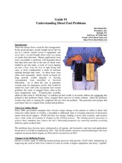
7 The flow diagram within figure one represents the general method created and currently used by GTSI for compressor and turbine sizing. Part 1 of this document, from this point forward, will limit its discussion to the TURBOCHARGER compressor analysis . The turbine PERFORMANCE analysis will be outline within Part 2. The process described within figure 1 is first conducted for the TURBOCHARGER centrifugal compressor. When a True value is obtained for the three decision blocks presented in figure 1 the compressor DESIGN procedure is complete. The same process is then followed for the TURBOCHARGER axial or radial turbine. Likewise, when a True value is obtained for the three decision blocks, the turbine DESIGN procedure is complete. The following discussion will proceed along this same path describing the procedure as it pertains to the compressor DESIGN cycle. Part 2 of this document will describe the procedure as it pertains to the turbine DESIGN cycle.
8 Figure 1: TURBOCHARGER Compressor and Turbine DESIGN 3 AIR SPECIFICATION The air specification dictates the combustion engines requirement for airflow rate as well as air and exhaust pressure. This specification will vary for different makes and models of combustion engines. Even for multiple, same model, natural gas combustion engines the air specification can vary depending on; 1) the local regulatory emission requirements, 2) style of aftermarket fuel injection and other associated equipment implemented, 3) ambient conditions the TURBOCHARGER will be operating within, and 4) the air specification authors method of calculating the required airflow rate and density needed to meet desired engine PERFORMANCE . This document typically includes, at a minimum, the following parameters for each DESIGN point the TURBOCHARGER is required to operate at: Barometric Pressure1 Ambient Temperature1 Intake Air Filtration Pressure Drop1 Compressor Discharge Pressure Turbine Inlet Pressure1 Turbine Inlet Temperature Turbine Discharge Pressure1 Air Mass Flow Rate Exhaust Mass Flow Rate It is worth noting that turbine inlet pressure is listed with a footnote identifying that its value within the air specification should appropriately represent the condition most difficult for the TURBOCHARGER to achieve.
9 Elaborating on this, a pressure drop across the system from TURBOCHARGER compressor discharge to TURBOCHARGER turbine inlet exists. In essence, this pressure drop represents the systems (combustion engine, inter-cooler, associated manifold piping, and applicable after treatment) inability to conserve the TURBOCHARGER compressor discharge pressure. The turbine converts static pressure to dynamic head allowing it to extract kinetic energy from the exhaust gas. With mass flow being conserved the pressure drop across the previously described system represents, in a very general sense, the energy available to the turbine versus the energy required by the compressor. A greater system pressure drop provides less energy for TURBOCHARGER use and strongly influences the overall machine DESIGN requirements. Though not covered by the scope of this document, the system differential pressure does provide an intrinsic benefit to engine operation by generating a pressure gradient across the power cylinder volume.
10 This pressure gradient enhances the displacement and/or entrainment of exhaust gasses. This action increases the mass of fresh air available for combustion during the following power stroke while also reducing cylinder operating temperatures. The accuracy of the air specification has significant importance for multiple reasons. First, it is possible to write the 1 indicates the operating condition most difficult for the TURBOCHARGER to achieve is that which is appropriately supplied within the air specification air specification in a manner, which reflects an extreme or impossible energy balance requiring the turbine to produce an unreasonable amount of energy. This of course, an incorrect practice, and typically a byproduct of the air specification writer attempting to use the TURBOCHARGER in a manner beyond which it was intended.