Transcription of Turnout Geometry - Gauge 0 Guild
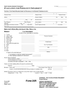
1 Issue 1 June 2004 Compiled by M. HollandTURNOUT GEOMETRYDATA SHEETT urnout Geometry1 GeneralThe terms used in Point and Crossing Work areillustrated in Figure 1 and defined in the table below. Note in particular that there are two definitions thatinclude the term Lead . Throughout this work, thedefinition of Lead , symbol LT, is the distance betweenthe Switch Heel and the Intersection of the GaugeLines. The other definition, symbol L, is the distancefrom the Switch Toe to the Noseof the crossing and isStock rail length LBSwitch radiusRSSwitch railStock railUsually5'4"- 5'5"but see textPlanedlength LPHeel length LHFull lead LHHeelI NGaugeintersectionTToeNoseLead LTNosedistance LNTurnout radiusRTHeel divergencehdHeel clearancehdRail width hrCheck railSplice railCrossinganglePoint railWing railsSwitchangle1 in a1 in Figure 1 Geometry of a turnoutreferred to as the Full Lead . The omission of the word Full can often cause confusion. The Switch Heel isthe point about which the switch blade theoreticallypivots; this may be a true pivot or merely a point at whichthe switch blade becomes free to bend.
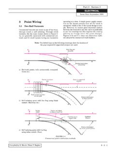
2 The location of theheel is determined by the amount of clearance required bywheels passing along the Stock Rail when the SwitchBlade is open. The complete list of symbols is as follows:-SYMBOLDEFINITIONDESCRIPTIONLFul l leadToe T to crossing nose H to Gauge intersection lengthToe T to heel distanceGauge intersection to crossing nose lengthToe T to end of switch planing rail lengthBetween joints with plain rail lengthToe T to closure rail head widthhcHeel clearanceDistance between adjacent faces of stock & switch divergenceDistance between running faces of stock and switch radiusRadius of curved portion of radiusRadius of Turnout (closure rail) angleBetween stock and tangent to switch angleBetween Gauge lines at intersection Switch TypesThere were three types of traditional switch, althoughmodern developments are creating variants. They arethe straight switch, the semi-curved switch and thecurved switch. See Figure Straight switch Note: the term Straight refers to the appearance of thewhole switch blade, and should not be confused with theterm Straight Cut which defines the cross section of theplaned area of the switch blade.
3 See Figure = hcStraight switchSemi curved switchCurved switchSwitch toeStock railSwitch railSwitchheelhd Heeldivergancehc HeelclearanceRailwidth5'4"- 5'5"LPLength ofplaning5'4"- 5'5"Straight partof stock railgauged tostraight railMinimumclearance =flangewayCurved portionof stock railSwitched radiusRSPlainingangle`Plained section sectionof switch isstraight Plained section sectionof switch isstraight SwitchheelSwitchheelThis section ofswitch is curved1 in aStraight stock railStraight stock railSwitchangleRail headwidthHCThis sectionof stock railis straightoffset atplainingangleLPLength ofplainingLPLength ofplaining5'4"- 5'5"MinimumflangewayclearanceSwitched radiusRS1 in aSwitchangleRail headwidthHCThis sectionof stock railIis curved atRS-GThis sectionof stock railis straightFigure 2 Types of Turnout type was used by most of the pre-groupingcompanies. Three variants (see Figure 3) for pivoting itexist, of which the most popular was the TongueSwitch. Here the fishplate by which the switch blade isattached to the Closure Rail provides the pivot.
4 In theHeel Switch, the blade meets its closure rail in a HeelChair that permits it to pivot while preventing it fromsliding out. This type was not in common use inbullhead track but is met in some FB track using a HeelBlock. The Spring Switch was a later development, inwhich the switch rail is secured in one or more Issue 1 June 2004 Compiled by M. HollandTURNOUT Curved switchThis was used by the GWR instead ofthe semi-curved switch. In this typethe entire switch was curved from toeto heel. They were designated B, Cand D, and corresponded to the semi-curved switches of the samedesignation. A, E and F sizes werenot used. For its long leads the GWRused a 30ft straight switch. BritishRailways used all six sizes in flatbottom form, albeit with slightlydifferent Geometry . More complexforms with transition curvature andplaning are in current use toaccommodate the higher speeds oftoday. 3 Switch switchThis term, often confused with the Straight Switch does not refer tothe switch Geometry , but to thevertical profile of the switch planingas viewed looking on the toe.
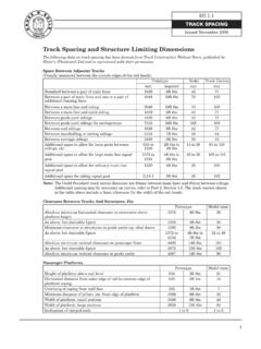
5 (Figure4) The switch rail is planed to athickness of at the toe and, inorder to avoid entry shock at a facingpoint, the stock rail is joggled also A later development is toplane the switch toe to and then chamfer the down to Flat bottom rail has too muchlateral stiffness to joggle and a housing is usuallymachined in the stockrail and chamfered switchesAnother principal type of switch end profile is the Undercut , in which the switch toe is planed down to afine edge at the top, the thickness being attainedlower down by the switch rail fitting under the head ofthe stock rail. More recently, both switch and stock railare being chamfered to provide greater strength at thetoe. (Figure 4)All three profiles are used for bullhead rail, but flatbottom switches are usually undercut or , the straight cut profile is the easiest for themodeller, using only hand tools, to produce. Many jogglesto house the switch, particularly in bullhead track, areoverdone, thereby spoiling the appearance of thetrackwork and some may prefer to file a tapered housingin the stock rail to correspond with the planing of theswitch rail as for flat bottom length LHTongue switchPivot is atfishplateFirstchairHeel length LHHeel length LHSpring switchFishplateFirstchairSwitch rail length LSHeel switchPivotis at chairSpecial"heel" chairFigure 3 Straight switch the joint with the closure rail and therefore theheel length LHis less than the switch rail length LS.
6 Insome installations, the switch rail began to curve inthese chairs and thus became an ancestor of the semi-curved switch. On main railways, the straight switchonly existed in bullhead form, although there are flatbottom installations in industrial sidings and switch sizes are in heel lengths of 6, 9, 12, 15,18, 24 and 30 feet, although the shorter ones are too rigidto be used as spring Semi-curved switchThis type began to be used after 1923 by the LPTB andall the mainline companies except the GWR. The bladeis straight for the length of the planing, after which itcurves at the nominal radius of the Turnout , to the pointat which it is joined to its closure rail. These switcheswere always of the sprung type and so LSexceeded theHeel Length, LHby at least 2ft 6in. Semi-curvedswitches were designated A, B, C, D, E and F andlargely superseded the 9, 12, 15, 18, 24 and 30 feetstraight switches respectively. A flat bottom versionexists in all but A SHEET44 Types of TurnoutsThere are three types of Turnout relevant to curved andsemi-curved switches, namely natural , compound and natural plus straight.
7 A natural Turnout is one wherethe Turnout radius RTand switch radius RSare equal. Acompound Turnout is one where RTis less than RS. Anatural plus straight Turnout has RTequal to RS, buthas a length of straight inserted between the end of theturnout curve and the Gauge intersection to increase thelead. Despite what many modellers believe, in themajority of cases the Turnout curve continued throughthe crossing. A straight crossing is easier for the modelsuppliers to produce and for the modeller to set out, butthose who do attempt a curved crossing will berewarded with track work that flows more with curved and semi-curved switches aredesignated by combining the switch type with thecrossing angle, B8 is a B switch and a 1 in 8crossing, similarly A7, C12 straight switches, there were several suitablecrossing angles for each switch, typical examples beingshown at Figure 2-8 on page 2-2-7. Although thisrepresents North British Railway track, that of othercompanies was not significantly different.
8 Even so, thosewishing to model a specific prototype and period arerecommended to study works covering the subject ingreater detail than is possible the exception of Scale 7, where the onlycompromises are due to minor differences in railheadwidth compared with the prototype, there aresignificant geometrical variations between model andprototype. Depending on the standards adopted theseprevent strict adherence to scaled down versions of fullsized Fine and Coarse standardsare under scale Gauge by 1mm. As aresult, a Turnout curve equating to aprototypical radius will generate anincorrect crossing angle and tomaintain the correct radius, thecrossing angle would have to bealtered. It is more practical to use theprototypical angle and change theturnout radius and this is therecommended method upon which theaccompanying calculations and tableshave been straight switch presentsparticular difficulties. Its prototypeheel clearance, hc, cannot be less thanflangeway clearance which is,prototypically, 13 This equates in Scale 7 but for Finestandard the value has to be increasedto and for Coarse standard This increases the heeldivergence and changes the switch angle, spring of theturnout curve and Turnout radius for a given crossingangle.
9 The effect is increased further when the wider code200 bullhead or code 220 flat-bottomed rail is used forCoarse standard trackwork. To illustrate the problem, inScale 7, a 6ft straight switch deflects an approachingvehicle though (1 in 16) at the toe, while in Finestandard the deflection is (1 in ). For Coarsestandard with a railhead width of the angle is (1 in 11) and this rises to (1 in 9) if the widecode 200/220 rail is used. This would have such an effectboth on smooth running through the Turnout and on itsappearance that some straight switches cannot berecommended although data has been given for those whowish to use is significant that ready made pointwork supplied inearlier times for Coarse standard and using the heavysection rail, approximated to fully curved switches,thereby giving a smoother run through the curved and semi-curved switches, the heelclearance exceeds the minimum flangeway for both Fineand Coarse standards where a rail head width of isused, and can be used satisfactorily, but B semi-curvedand GWR fully curved bull head switches can giveproblems of flangeway clearance when wide railis used due to its greater on space generally prevent mostmodellers from using all but the shortest switches andcrossing angles.
10 (To keep the data sheet tables withinbounds the longest Turnout listed is a B8, which has aclosure rail radius of about 4270mm or 14ft). Once thebasic design of a layout has been completed the types ofturnouts required can be determined. This can be done bymeasuring the crossing angle and selecting a suitable pairof switches from the range suggested in Table 1 2, on page 6, covers the range of switches in 4 End views of straight, undercut and chamfered switches. Note thatthe flat bottomed rail versions requires the rail foot to be machined toaccommodate the switch. Of the three versions, modellers will find thestraight cut version generally easier to Issue 1 June 2004 Compiled by M. HollandTURNOUT GEOMETRY56 Other Data SheetsThe layouts of the various switch types are detailed in Data Sheets , 2 and suitability of the chosen combination of switch and crossing angle can be checked with the Turnout Curve Tableson Data Sheets that show the overall length and Turnout (closure rail) radius.


![Ipdp-am¬, Xe-t°m-´p-Ic ]n. H. t^m¨ : 04885- 272743 ...](/cache/preview/7/7/8/3/3/4/c/b/thumb-778334cb1b32aeb6855223468bb3e6ba.jpg)