Transcription of Tutorial on How to Do FEA in ProE - University of …
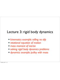
1 Tutorial on How to Do FEA in ProE Xi Chen November 2015 1. Introduction 2. Basics of FEA 3. Instructions on How to Do FEA in ProE FEA Procedures in ProE How to Build a Structural Model in ProE Defining Load in FEA Defining Constraints in FEA Assigning Materials to Parts in FEA FEA Analysis and Study 4. Summary 1. Introduction BothProEandSolidWorksarepopularCADsoftwa resformechanicaldesignandanalysis includingFEA(finiteelementanalysis).InOP TI521class,howtobuildFEAmodulesandrun ,alotofcompaniesuseProEinsteadof SolidWorkssinceProEcouldhandlemorecompli catedpartsandfeaturesespeciallyfor ,Iwilldescribehowtobuild provide instruction and guidance on how to do FEA in ProE to mechanical engineers.
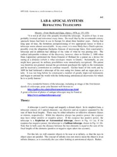
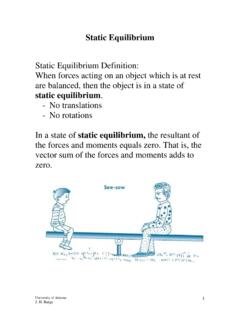
2 2. Basics of FEA FEA(finiteelementanalysis)cutsastructure intoalotofelements(piecesofthestructure) . Thentheseelementsarere connectedat nodes asifnodeswerepinsordropsofgluethat These equations could be expressed as matrix equation: {u}={F} Eq. (1)K[] Forelasticproblem,Kisapart sstiffness, thermal problem, K is material s thermal conductivity, u is temperature and F is heat flux. Figure 1 FEA Basics: parts are decomposed of elements and nodes Displacement at each element could be solved as: { Eq. (2)}] {F} uE=[KE 1E together,thefieldquantitybecomesinterpol atedovertheentirestructureinpiecewise equationisshowninEqu.(2).
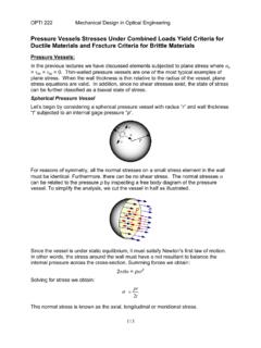
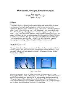
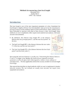
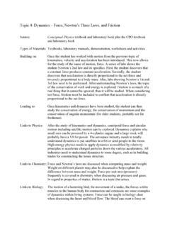
3 [K] ,the Kij=Kji displacementatpointiduetoan unitloadatanotherpointjisequaltothedispl acementatj duetoan unitloadati,providedthatthedisplacements andforces correspond, ,thatthey [K]( iszero, uniquedisplacement{u}et[K]) d=0 solutions. This happens for underconstrained systems. Figure 2 Stiffness matrix, displacement and force relationship Bysolvingthestiffnessmatrixequation,FEAc ouldhandlesolidmechanics, dynamics ,heat ,FEAprovides approximate inherent ,theerrorscouldbemadeby ,fieldquantityisassumedtobeapolynomialov eranelement which is not true. 1 Figure 3 Illustrations of different types of elements approximation TheFEAalgorithmusesverysimpleintegration algorithmtodointegrationwhichcauseserror s.
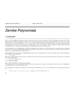
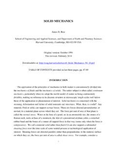
4 Alsowhenthereisverylargestiffnessdiffere nceinasystem, inspection and intuition of the FEA results is very important. Figure 4 Ill conditioned system (too large difference in stiffness k 1 and k 2 ) 3. Instructions on How to Do FEA in ProE , ,IwillintroducehowtodoFEAin ProE step by step with a beam example. FEA Procedures in ProE processes:(1) ,loadsand (2) Performingandrunninganalysisandreviewing results.(3)Varyingparametersandoptimizin g the design. ,themodelisbroken actualsizeandshapeoftheelementsdependont hemodel,andeachelementhasafinite numberofdegrees of freedom(DOF).
5 Thesimultaneousequationsandboundarycondi tionsof , orelementsthatsharenodes, arefoundusingpiecewisepolynomialinterpol ationoraseriesofdifferentialequations, 2 the results are reviewed and, if necessary, the model is optimized. Figure 5 ProE FEA Procedure Forpreprocessingstep,oneneedselectanalys istypesuchasstructurestaticanalysis,moda l analysis,transientdynamicanalysis,buckli nganalysis,contact,steady statethermalanalysisor Dor3 D,linearor quadratic,truss,beam,shell, ProEmakesnodes,buildselementsbyassigning connectivityatnodesandapplyboundary conditions and loads. create nodes build elements by assigning connectivity at nodes apply boundary conditions (constraints) and loads Table 1 FEA Preprocess steps 3 How to Build a Structural Model in ProE Inthissection,theproceduresonhowtobuilda structuralmodelforFEAanalysisare ,staticanalysisisdoneonthesamebeamwithth ermal gradient load instead of force load to illustrate how to calculate thermal stress in ProE.
6 TorunFEAinProE, accesstoFEAtoolwhichisprovokedbyclicking Tool>Simulate ProE to run FEA is shown in Fig. 6 below. Figure 6 ProE FEA Tool Simulate (Click Simulate for structural and thermal FEA from ProE) TherearetwoFEAmodesthatcouldbeselected: StructureMode or ThermalMode inProE. Inthisreport, Chamfers androundsareusuallyignoredtosimplifysyst em .Ifoneisuncertainaboutwhatparts shouldbekeptandwhatpartsarenecessaryinor dertocreateanaccurateanalysis,onecan usethe Inheritanceand advantageofnonessentialcutsandmaterialan dwillsavetimeandmoneywhileeasing ,notethatinordertosavemeshingandanalysis time,differenttypesof symmetrical.
7 TodoFEAanalysis,oneneedfirstbuildthestru cturalmodel. Themodelneedinclude definingconstraints, ,one couldrun analysisandstudies forstatic,modal,buckling, ProE FEA modeling for a fixed end beam is shown in Fig. 7 4 Figure 7. ProE FEA Model User Interface Defining Load in FEA Tobuildthemodel,letusfirstdefinethe including Force/Moment , Pressure , Gravity , Bearing , CentrifugalLoad , Temperature Load and Preload Force/Moment .Forexample,I applied 10 Nalongthey axis(greenarrowdirection)ontheendsurface highlightedingreenin Fig. 7. The definition of this force in ProE is shown in Fig. 8. Therearealsootherkindsofloads ,onecouldselectabearing loaddistribution,amoreaccuraterepresenta tionofthereal , thesoftwarecancalculatetheradialforceort orqueneededtosatisfythedefinedrequiremen ts ,onecanincludethatintheanalysisaswellbyd efining gravity onthepartcanbelinearorfunction driven,allowingtheloadtobeinterpolatedov erentitiesor ,then temperatureconditions,auniformtemperatur e.
8 Temperaturespatialvariationdefinedbya functionorimportedtemperaturefieldcanbeu sedtoproperlymodelthedeformationand 5 beam sy , ProE,thex axisisalwaysshownasredarrow,they axisisingreenarrowandthez axisisin blue arrow. Once loads are defined, the loads are shown on the part. Figure 8 Defining a force/ moment in ProE Figure 9 Bearing Load Example 6 Figure10 TemperatureLoadDefinition.(temperaturesp atialvariationisdefinedbyafunction: f(x)=75+y/10 Valueof1issetsincefunctionf(x)fullyrepre sentsthetemperaturedifference betweenthebeamsurfacesalongthey axisandnoscalingfactorisneeded Reference temperature is set as 75F since the zero thermal stress is at 75F.)
9 Defining Constraints in FEA Next,oneneeddefine endconstrainton ,y andztranslationsneedbechosenas fixed insteadof free or prescribed .Oncethe constraint is defined, one could see constraint symbol on the part where constraints are applied. 7 Figure 11 Displacement Constraint Definition ,three thePinconstraintdialogbox,onecouldchoose eitherfixedorfreeangularconstraintandfix ed screws/ bolts. 8 Figure 12 Example of Part with Pin Constraints Table 2 Pin Constraints Aballconstraintrepresentsaballjointinwhi chtranslationisfixedwhilerotationisfree. enablesonetocreateaconstraintthatallowsf ullplanarmovement,butconstrainsoff plane thesefourkindsofconstraints,thereisalsoM irrorSymmetryConstraintswhichenablesonet o symmetryallowsonetotakeadvantageofthemod el'ssymmetrytoreducemeshingand symmetrysuccessfullytoanalyzethemodel,th epartorassemblymustexhibitreflective ,one should run the modal analysis with the entire model without mirror symmetry constraints.
10 9 Assigning Materials to Parts in FEA TorunFEAanalyses,oneneed material from the dialog box. FEA Analysis and Study File menu,onecouldchooseanalysisamong newstatic , new modal , newbuckling , newfatigue , newprestress , newdynamic andsensitivityand optimization studies. Figure 13 FEA Analyses and Studies Dialog Box Newstaticanalysisallowsonetoanalyzepart analysisprovidestheresonantfrequenciesan ddeflectionandstressdistributionforselec ted Newdynamicallowsonetocalculatethesafetyf actorforspecifiedaccelerationthatthepart endbeamdeflectiondistributionunder(a)a10 N (b) 10 , calculations.