Transcription of Tuxedo Touch Series Home Automation System Installation ...
1 800-08221 7/11 Rev. A TTTTTTTT uuuuuuuuxxxxxxxxeeeeeeeeddddddddoooooooo TTTTTTTT oooooooouuuuuuuucccccccchhhhhhhh SSSSSSSS eeeeeeeerrrrrrrriiiiiiiieeeeeeeessssssss HHHHHHHH oooooooommmmmmmmeeeeeeee AAAAAAAA uuuuuuuuttttttttoooooooommmmmmmmaaaaaaaa ttttttttiiiiiiiioooooooonnnnnnnn SSSSSSSS yyyyyyyysssssssstttttttteeeeeeeemmmmmmmm Installation and Setup Guide Table of Contents iii About the 1 Safe Mode .. 1 1 Software Upgrades .. 2 Mounting .. 3 Wiring .. 4 Specifications: .. 5 Front Panel LEDs .. 5 Navigation Icons .. 6 Panel Fault Displays .. 7 Initial 8 Programming the Control Panel .. 8 Keypad Initialization .. 8 Time and Date Setup .. 9 Night Setup .. 9 Web Server/Hosting .. 9 IP Setup .. 9 11 Brightness and Volume 11 Display & Audio Setup .. 11 Operating 11 Adjust the Screen Timeouts .. 12 Clean Screen .. 12 13 Picture 13 Camera 14 Video (Audio) Setup.
2 15 System 17 CS Setup .. 17 ECP Address Selection .. 17 CS Options / Operating 18 Operating 18 Screen Security .. 19 Code Authority .. 20 Device 20 Panel 20 User System 21 How to Add a User .. 22 Table of Contents (cont d) iv How to Add an Existing User to a Second 22 How to Delete a User .. 22 Time/Date Setup .. 23 Setting Daylight Savings Time .. 23 Setting Current Time and Date .. 23 Advanced Setup .. 24 System Information .. 24 Keypad 24 Keypad 24 LED Test .. 25 Calibration Test .. 25 Z-Wave 26 NIGHT Setup Function .. 27 Output Setup 27 28 Including/Adding Z-Wave Devices ..28 Include/Add a Light, Switch or Outlet Module .. 28 Include a Door Lock .. 29 Include a honeywell 29 Editing Z-Wave Device Names .. 30 Edit a Device Module 30 Exclude/Delete Z-Wave 30 Exclude a Light, Outlet, or Switch Module .. 30 Exclude a Door Lock Device .. 31 Exclude a honeywell Thermostat ..31 Exclude All Z-Wave 32 Abort a Z-Wave 32 Creating a Scene.
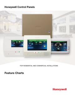
3 33 Create a Room .. 35 Setting a Secondary Controller .. 35 Updating Controllers with New or Removed devices .. 36 Removing a Secondary Controller ..36 Z-Wave 36 Compatible 37 Important 38 1 About the System This guide provides information to install and set-up honeywell s Tuxedo Touch Series home Automation and Security System . The graphical Touch -screen keypads are Advanced User Interface (AUI) devices, which combine home Automation and home security. Your System may consist of one or more of the following: TUXS Keypad (black/silver housing) TUXW Keypad (white housing) One or more other keypads for System control Various sensors for perimeter and interior burglary protection, plus a selected number of strategically placed smoke, carbon monoxide or combustion detectors Lighting/output devices. Equipped with web-hosting capability and built-in Z-Wave technology, the Tuxedo Touch Keypad can be used to control the home environment, such as lights, appliances, thermostat, door locks and cameras via any web enabled device (PC, Smart Phone and Tablet).
4 Note: To the installer, see the "Important Notes" in the Important Notes section of this guide. Safe Mode The keypad contains a Safe Mode of operation. In the rare event that the keypad cannot successfully communicate in its graphic mode with the control panel, the Safe Mode is a backup mode that ensures that you can communicate with your System . In this mode, the keypad operates much like a standard non-graphic keypad so that you can control your System until the problem is corrected. DO NOT perform panel programming while in the Safe Mode. Performing panel programming while in the Safe Mode may cause the panel and keypad to become out of sync. DO NOT use several hardwired motion detectors in high traffic locations. The high quantity of signals received by the panel may cause the keypad to enter the Safe Mode. Compatibility The below listing identifies the alarm systems that the keypad can interface with, the maximum number of keypads that can be used with each System , and the minimum alarm panel software revision level for compatibility.
5 Note: For SIA installations used with a VISTA-128 BPTSIA Control, see the SIA CP-01 Quick Reference Chart, Document # 800-09699 located at: . Alarm System Maximum Number of Keypads Minimum Software Revision Level VISTA-15P 2 VISTA-20P 2 VISTA-20P 4 VISTA-21IP 4 VISTA-128BP 3 VISTA-128 FBP 3 VISTA-128 FBP-9 3 About the System (cont d) 2 Alarm System Maximum Number of Keypads Minimum Software Revision Level VISTA-250 FBP-9 3 VISTA-250BP 3 VISTA-250 FBP 1 VISTA-250 FBP 3 VISTA-128 BPE 3 VISTA-250 BPE 3 VISTA-128 BPEN 3 VISTA-128 BPLT 3 VISTA-128 FBPN 3 VISTA-128 BPT 6
6 VISTA-250 BPT 6 VISTA-128 BPTSIA 6 FA148CP 2 FA168 CPS 4 FA1660C 3 3 FA1660CT 6 FA1670C-9 3 FA1700C 3 3 Note: Keypad may only be used in the following UL/cUL installations: UL 365, UL609, UL 985, UL1023, UL 1610, CAN/ULC-S303, CAN/ULC-S304, ULC-S545, ULC/ORD-C1023, and ANSI/SIA CP-01-2010. On all panels except the residential panels, you may obtain the software revision level of the alarm panel by entering the program mode and then entering #92 on the keypad.
7 This can be done from the Console Mode or a standard alpha keypad, if supplied. The second line of the keypad displays the software revision level (w/out the decimal point). The keypad sound suppression feature available in some commercial panels is not compatible with the Tuxedo Touch keypad. The Voice Chime feature is a residential control feature only. Note: If using the maximum number of keypads, an additional auxiliary power supply may be needed. Software Upgrades IMPORTANT: During the Installation process, check the latest software version and if necessary go to MyWebTech to download the latest upgrade for your specific keypad model. About the System (cont d) 3 Mounting This keypad is for indoor use only and should be mounted at a comfortable viewing level. Avoid mounting in areas of high condensation such as bathrooms or in locations where bright light or sunlight shines directly on the screen. The keypad can be mounted with or without the mounting plate.
8 Use the center securing screw for European installations. Mounting with mounting plate: 1. Select a mounting location. 2. Detach the mounting plate by sliding downward. 3. Use the mounting plate to mark the location of the mounting holes on the mounting surface and check for level. 4. Locate the mounting plate over the mounting surface such that the wire/cable access openings are aligned while passing the wires/cable through the case back. **Go to Wiring (next page) and complete wiring**5. Secure the mounting plate to mounting surface using 4 screws (supplied). 6. Slide keypad onto mounting plate. 6280-006-V0 WALLSURFACEWALLMOUNTINGPLATE(OPTIONAL)MO UNTINGSCREWS (4)(TYP) Mounting without mounting plate: 1. Select a mounting location. 2. Detach the mounting plate by sliding downward and discard. 3. Use the template (provided in the carton) to mark the location of the mounting screws and the cut-out for the keypad assembly on the mounting location.
9 Check for level. 4. Install 4 screws (supplied) in the mounting surface leaving screw heads 1/8 above the mounting surface. 5. Locate the case back over the mounting surface such that the opening is aligned with the wire/cable access opening on the mounting surface while passing the wires/cable through the opening in the case back. **Go to Wiring (next page) and complete wiring** 6. Mount keypad by sliding onto the screw heads. 4 - 3/4"3 - 9/16"800-08831 5/11 LOCATIONDRILL 3/16" DIA. HOLES4 PLACES 800-00831u 6280 Series CASE BACK MOUNTING TEMPLATEDRILL 3/16" DIA. HOLE6280-016-V0 MOUNTINGSCREWSINSTALLED1/8 ABOVESURFACETEMPLATEWALLSURFACE Mounting (European Installations) using a center securing screw: 1. Detach case front by removing the two bottom screws. Gently pull up using a screwdriver if necessary and pry apart. Lift off cover. 2. Mount the keypad in its final location, (see Standard Mounting or Mounting without the mounting plate ) install center securing screw (supplied) and tighten to mounting surface.
10 3. Replace the case front and secure using the two bottom screws. 6280-015-V0 INSTALL CENTERSECURING SCREWDETACH CASE FRONTBY REMOVING SCREWS (2)AND LIFT UPCASEFRONTCASEBACK About the System (cont d) 4 Wiring Connect the Tuxedo Touch in parallel with keypads and other peripheral devices using the keypad data (ECP) bus. If the Tuxedo Touch is used as the primary System keypad, maximum wire run length is 150 feet. If more than one keypad is wired to one run, then the maximum lengths must be divided by the number of keypads on the run. ( , the maximum length is 75 feet if two keypads are wired on a #22 gauge run). Wire Gauge: Length #22 gauge 150 feet #20 gauge 240 feet #18 gauge 350 feet #16 gauge 550 feet Connect the wires to the keypad terminal block as shown below. BLACKPOWER FROM SUPPLEMENTARYPOWER SUPPLY IF USEDRED BLACKGREENYELLOWCONTROLTERMINAL STRIPSUPPLEMENTARY+12 VDCPOWER SUPPLYP/N AD12612 BLACK (GND)RED (+12 VDC) GREEN( DATA TOCONTROL)YELLOW(DATA FROMCONTROL)CONTROLTERMINAL STRIPAU XDATAINDATAOUTAUXDATAINDATAOUTAUXAUXYG62 80i-002-V0RJ45IP CONNECTION IMPORTANT: When the keypad is powered from an auxiliary power supply, always apply power to the control panel first and then the keypad.


