Transcription of Two Case Studies on Soil Nailed Slope Failures
1 -1-Two Case Studies on soil Nailed Slope Failures Liew, Shaw-Shong1 & Liong, Chee-How2 1 Director, Gue & Partners Sdn Bhd, Kuala Lumpur, Malaysia 2 Senior Engineer, Gue & Partners Sdn Bhd, Kuala Lumpur, Malaysia 39-5 Jalan 3/146, The Metro Centre, Bandar Tasik Selatan, 57000 Kuala Lumpur, Malaysia e-mail: Abstract The use of soil nails for Slope strengthening works has been gaining popularity in Malaysia since its first application in 1980s in view of the attractive benefits of simple and fast installation method to reinforce steep cut Slope . Prior to design, it is of utmost importance that subsurface investigation be carried out to determine the subsoil profile and the relevant engineering parameters.
2 soil Nailed Slope design in accordance to established procedures could then be performed with better confidence after the investigation. This paper presents the investigation results of two soil Nailed Slope Failures in Malaysia and discussion on the lessons learned from these two Failures . The first failure site (Site A) is underlain by completely weathered Shale facies, with the existence of mudstone and siltstone. The failure consisted of seven upper berms of 1V:1H cut Slope (a total of 42m in height) and five lower berms of 4V:1H soil Nailed Slope (total of 30m in height) reinforced with 12m length soil nails.
3 When the Slope failure occurred, all the soil nails except for the soil nails at the lowest berm had been installed. The geology of the second failure area (Site B) consists primarily of weathered metamorphic rock with massive granitic intrusion. The failure involved a steep soil Nailed Slope (4V:1H) up to a total Slope height of seven and a half berms, with the maximum height of about 45m. The top Slope was reinforced with 6m length soil nails, and the lower Slope were reinforced with 12m length soil nails. During the investigation, additional subsurface investigation works were also carried out to confirm the subsoil profile and shear strength parameters.
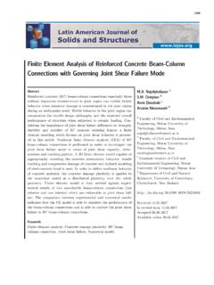
4 The investigation results reveal that the first failure was due to inadequate Factor of Safety (FOS) for global stability and the mechanism of progressive failure . The dominant cause for the second failure is attributed to facing failure at the soil nail head. Keywords: Facing failure , nail head, progressive failure , soil nail 1. CASE HISTORY A failure OF FIVE BERMS soil Nailed Slope + SEVEN BERMS CUT Slope The original Slope consisted of the upper cut Slope and lower soil Nailed Slope with the following configuration as shown in Figure 1: a) Seven upper berms of 1V:1H cut Slope with a 2m width berm provided at every 6m height interval.
5 The total Slope height was 42m. b) Five lower berms of 4V:1H soil Nailed Slope with a 2m width berm provided at every 6m height interval. The Slope was reinforced with 12m length soil nails and the total Slope height was 30m. These cut Slope and soil Nailed Slope were constructed to facilitate the formation of a new road. -2-Topography and Geological Condition The site is located on high ground with reduced level ranging from RL210m to RL330m. Based on the draft geological map interpreted by Mineral and Geoscience Department, Malaysia (1974), the site is underlain by Shale facies. This facies consist of mudstone and siltstone.
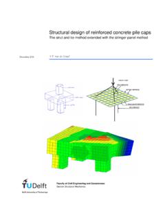
6 Figure 1: Designed Slope Profile and Remedial Slope Profile Figure 2: Front View of Failed Slope Site Conditions and Observations During the geological mapping and subsurface investigation works after the failure , it was observed that the cut Slope face varied from a relatively smooth surface to irregular rough surface. In general, the site was dry and no water seepage was observed. The geological mapping reveal that the joint sets mapped at the Slope surface were daylighting towards the main road as shown in Figure 3. These unfavourable joint sets were likely contributing to the Slope failure . Joints with in-filling material like iron oxide and silt were also observed as captured in Figure 4.
7 Most of the exposed materials on the Slope surface were Grade III to V. Figure 3: Daylighting Joint Sets towards Main Road Figure 4: Joints with Infilling Material Subsurface Investigation and Laboratory Tests A subsurface investigation consisting of two boreholes and relevant laboratory tests were planned and implemented to establish the subsoil profile and obtain necessary soil strength parameters. The locations of the boreholes and the interpreted subsoil profile are shown in Figures 5 and 6 respectively. Figure 5: Layout Plan showing Borehole Locations Figure 6: Interpreted Subsoil Weathering Profile -4-A series of laboratory tests was carried out on the samples recovered from the subsurface investigation works.
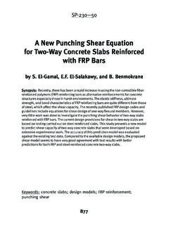
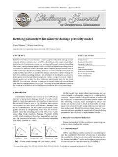
8 The tests included Atterberg limits, particle size distribution, multiple reversal shear box test, Consolidated Isotropically Undrained (CIU) triaxial test with pore pressure measurements and petrographic analysis. Selected test results are presented in the following section. 02505007501000125015001750200022502500 Normal Stress, kPa0250500750100012501500175020002250250 0 Shear Stress, kPaLegendShear Box (BH2-MZ2)CIU (BH2/MZ2-S1)CIU (BH2/MZ2-S2)CIU (BH2/MZ2-S3)CIU (BH2/MZ3-S1)CIU (BH2/MZ3-S2)CIU (BH2/MZ3-S3)0250500750100012501500175020 0022502500025050075010001250150017502000 22502500 Residual Strength (c'r = 0, 'r = 33o)Peak Strength (c'p = 30, 'p = 39o) 050100150200250300350400450500550600 Normal Stress, kPa050100150200250300350400450500550600 She ar Stre ss, kPa0501001502002503003504004505005506000 50100150200250300350400450500550600 LegendShear Box (BH1-MZ1)CI U (BH1/MZ1-S1)CI U (BH1/MZ1-S2)CI U (BH1/MZ1-S3)
9 Residual Strength (c'r = 0, 'r = 33o)Peak Strength (c'p = 30, 'p = 33o) Figure 7: Effective Shear Strength for Grade III Material Figure 8: Effective Shear Strength for Grade IV Material Based on the British soil Classification System, most of the tested samples are silt of intermediate to high plasticity. Three sets of CIU tests were also carried out on samples of Grade III and IV material. In addition, two multiple reversal direct shear box test were also performed on the reconstituted samples from the CIU specimens. The results of both the CIU and shear box tests are shown in Figures 7 and Figure 8.
10 Table 1 summarises the peak and residual strength parameters from the tests. Table 1: Peak and Residual Strength of Grade III and IV Materials Weathering Grade Effective cohesion, c Effective friction angle, Peak 30 kPa Peak 33o Grade IV Residual 0 kPa Residual 33o Peak 30 kPa Peak 39o Grade III Residual 0 kPa Residual 33o Rainfall Record Rainfall record was obtained for the failure area and it was found that there was no record of abnormal high rainfall before the Slope failure event.