Transcription of Two-Way Joist Concrete Slab Floor (Waffle Slab) System ...
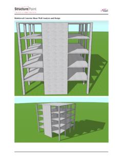
1 Version: May-18-2017 Two-Way Joist Concrete slab Floor ( waffle slab ) System analysis and design Version: May-18-2017 Two-Way Joist Concrete slab Floor ( waffle slab ) System analysis and design design the Concrete Floor slab System shown below for an intermediate Floor with partition weight of 50 psf, and unfactored live load of 100 psf. The lateral loads are independently resisted by shear walls. A flat plate System will be considered first to illustrate the impact longer spans and heavier applied loads. A waffle slab System will be investigated since it is economical for longer spans with heavy loads. The dome voids reduce the dead load and electrical fixtures can be fixed in the voids. waffle System provides an attractive ceiling that can be left exposed when possible producing savings in architectural finishes. The Equivalent Frame Method (EFM) shown in ACI 318 is used in this example.
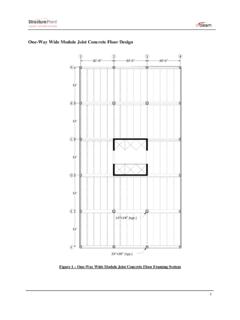
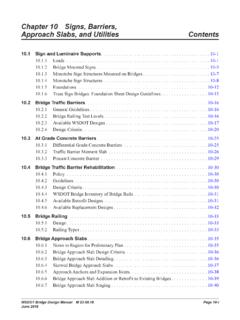
2 The hand solution from EFM is also used for a detailed comparison with the model results of spSlab engineering software program from StructurePoint. Figure 1 - Two-Way Flat Concrete Floor System Version: May-18-2017 Contents 1. Preliminary Member Sizing .. 1 2. Flexural analysis and 13 Equivalent Frame Method (EFM) .. 13 Limitations for use of equivalent frame 14 Frame members of equivalent frame .. 14 Equivalent frame analysis .. 17 Factored moments used for design .. 19 Factored moments in slab -beam strip .. 21 Flexural reinforcement 22 Factored moments in columns .. 26 3. design of Columns by spColumn .. 28 Determination of factored loads .. 28 Moment Interaction Diagram .. 30 4. Shear Strength .. 34 One-Way (Beam action) Shear Strength .. 34 At distance d from the supporting column .. 34 At the face of the drop panel .. 35 Two-Way (Punching) Shear Strength .. 37 Around the columns faces.
3 37 Around drop panels .. 40 5. Serviceability Requirements (Deflection Check) .. 45 Immediate (Instantaneous) Deflections .. 45 Time-Dependent (Long-Term) Deflections ( lt) .. 57 6. spSlab Software Program Model Solution .. 58 7. Summary and Comparison of design Results .. 80 8. Conclusions & Observations .. 83 1 Code Building Code Requirements for Structural Concrete (ACI 318-14) and Commentary (ACI 318R-14) Reference Concrete Floor Systems (Guide to Estimating and Economizing), Second Edition, 2002 David A. Fanella, Portland Cement Association. PCA Notes on ACI 318-11 Building Code Requirements for Structural Concrete , Twelfth Edition, 2013, Portland Cement Association. Simplified design of Reinforced Concrete Buildings, Fourth Edition, 2011 Mahmoud E. Kamara and Lawrence C. Novak Control of Deflection in Concrete Structures (ACI 435R-95), American Concrete Institute Reinforced Concrete design .
4 Hassoun, McGraw Hill design Data Story Height = 13 ft (provided by architectural drawings) Superimposed Dead Load, SDL = 50 psf for Frame walls, hollow Concrete masonry unit wythe, 12 in. thick, 125 pcf unit density, with no grout ASCE/SEI 7-10 (Table C3-1) Live Load, LL = 100 psf for Recreational uses Gymnasiums ASCE/SEI 7-10 (Table 4-1) fc = 5000 psi (for slab ) fc = 6000 psi (for columns) fy = 60,000 psi Solution 1. Preliminary Member Sizing Preliminary Flat Plate (without joists ) a. slab minimum thickness Deflection ACI 318-14 ( ) In lieu of detailed calculation for deflections, ACI 318 minimum slab thickness for Two-Way construction without interior beams is given in Table For flat plate slab System , the minimum slab thickness per ACI 318-14 are: 376 Exterior Panels: ACI 318-14 (Table ) But not less than 5 in. ACI 318-14 ( (a)) 376 Interior Panels: ACI 318-14 (Table ) But not less than 5 in.
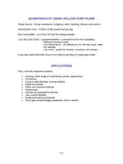
5 ACI 318-14 ( (a)) Where ln = length of clear span in the long direction = 33 x 12 20 = 376 in. Use 13 in. slab for all panels (self-weight = 150 pcf x 13 in. /12 = psf) 2 b. slab shear strength one way shear Evaluate the average effective depth (Figure 2): Where: cclear = 3/4 in. for # 6 steel bar ACI 318-14 (Table ) db = in. for # 6 steel bar Figure 2 - Two-Way Flat Concrete Floor System Factored dead load, ( 50) 255 psfDuq Factored live load, 100 160 psfLuq ACI 318-14 ( ) Total factored load, 255 160 415 psfuq Check the adequacy of slab thickness for beam action (one-way shear) ACI 318-14 ( ) at an interior column: Consider a 12-in. wide strip. The critical section for one-way shear is located at a distance d, from the face of support (see Figure 3): are for one-way shear is ft22 121212 TributaryA kipsuuTributaryVqA '2ccwVf b d ACI 318-14 (Eq.)
6 Where 1 for normal weight Concrete 3 2 kips1000cuVV slab thickness of 13 in. is adequate for one-way shear. c. slab shear strength Two-Way shear Check the adequacy of slab thickness for punching shear ( Two-Way shear) at an interior column (Figure 4): 2220 area for Two-Way shear is(33 33)1082 ft12 TributaryA 1082 kipsuuTributaryVqA '4 (For square interior column)ccwVf b d ACI 318-14 (Table (a)) kips1000cV kipscuVV slab thickness of 13 in. is not adequate for Two-Way shear. This is expected as the self-weight an applied loads are very challenging for a flat plate System . Figure 3 Critical Section for One-Way Shear Figure 4 Critical Section for Two-Way Shear In this case, four options can be considered: 1) increase the slab thickness further, 2) use headed shear reinforcement in the slab , 3) apply drop panels at columns, or 4) use Two-Way Joist slab System .
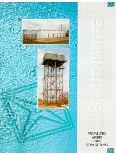
7 In this example, the latter option will be used to achieve better understanding for the design of Two-Way Joist slab often called Two-Way ribbed slab or waffle slab . Check the applicable Joist dimensional limitations as follows: 1) Width of ribs shall be at least 4 in. at any location along the depth. ACI 318-14 ( ) Use ribs with 6 in. width. 4 2) Overall depth of ribs shall not exceed times the minimum width. ACI 318-14 ( ) x 6 in. = 21 in. Use ribs with 14 in. depth. 3) Clear spacing between ribs shall not exceed 30 in. ACI 318-14 ( ) Use 30 in. clear spacing. 4) slab thickness (with removable forms) shall be at least the greater of: ACI 318-14 ( ) a) 1/12 clear distance between ribs = 1/12 x 30 = in. b) 2 in. Use a slab thickness of 3 in. > in. Figure 5 joists Dimensions In waffle slabs a drop panel is automatically invoked to guarantee adequate Two-Way (punching) shear resistance at column supports.
8 This is evident from the flat plate check conducted using 13 in. indicating insufficient punching shear capacity above. Check the drop panel dimensional limitations as follows: 1) The drop panel shall project below the slab at least one-fourth of the adjacent slab thickness. ACI 318-14 ( (a)) Since the slab thickness (hMI calculated in page 7 of this document) is 12 in., the thickness of the drop panel should be at least: 12 3 , minhh Drop panel depth are also controlled by the rib depth (both at the same level).For nominal lumber size (2x), hdp = hrib = 14 in. > hdp, min = 3 in. The total thickness including the actual slab and the drop panel thickness (h) = hs + hdp = 3 + 14 = 17 in. 2) The drop panel shall extend in each direction from the centerline of support a distance not less than one-sixth the span length measured from center-to-center of supports in that direction.
9 ACI 318-14 ( (b)) 5 11113333 11 ft66661,dp_min11L LL 11113333 11 ft66662,dp_min22L LL Use 12 ft > 11 ft1,dp2,dp1,dp_min2,dp_minL= L=L L Based on the previous discussion, Figure 6 shows the dimensions of the selected Two-Way Joist System . 6 Figure 6 Two-Way Joist ( waffle ) slab 7 Preliminary Two-Way Joist slab ( waffle slab ) For slabs with changes in thickness and subjected to bending in two directions, it is necessary to check shear at multiple sections as defined in the ACI 318-14. The critical sections shall be located with respect to: 1) Edges or corners of columns. ACI 318-14 ( (a)) 2) Changes in slab thickness, such as edges of drop panels. ACI 318-14 ( (b)) a. slab minimum thickness Deflection ACI 318-14 ( ) In lieu of detailed calculation for deflections, ACI 318 Code gives minimum slab thickness for Two-Way construction without interior beams in Table For this slab System , the minimum slab thicknesses per ACI 318-14 are: 376 Exterior Panels: ACI 318-14 (Table ) But not less than 4 in.
10 ACI 318-14 ( (b)) 376 Interior Panels: ACI 318-14 (Table ) But not less than 4 in. ACI 318-14 ( (b)) Where ln = length of clear span in the long direction = 33 x 12 20 = 376 in. For the purposes of analysis and design , the ribbed slab will be replaced with a solid slab of equivalent moment of inertia, weight, punching shear capacity, and one-way shear capacity. The equivalent thickness based on moment of inertia is used to find slab stiffness considering the ribs in the direction of the analysis only. The ribs spanning in the transverse direction are not considered in the stiffness computations. This thickness, hMI, is given by: 1/ 31/ 31212 513512 spSlab Software Manual (Eq. 2-11) Where: Irib = Moment of inertia of one Joist section between centerlines of ribs (see Figure 7a). brib = The center-to-center distance of two ribs (clear rib spacing plus rib width) (see Figure 7a).