Transcription of Type 667 Diaphragm Actuator Sizes 30-76 and 87
1 667 Diaphragm Actuator Sizes 30-76 and 87 ContentsIntroduction2.. Scope of Manual2.. Description2.. Specifications3.. Maximum Pressure Limitations3.. Installation4.. Mounting the Actuator on the Valve5.. Discussion of Bench Set6.. Bench Set Spring Adjustment6.. For Direct Acting Valves (PDTC)7.. For Reverse Acting Valves (PDTO)7.. Installing the Stem Connector Assembly8.. Deadband Measurement9.. Loading Connection9.. Maintenance9.. Actuator10.. Actuator Disassembly10.. Actuator Assembly11.. Top-Mounted Handwheel Assembly (Adjustable Down Travel Stop)11.
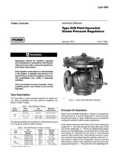
2 Disassembly for Top-Mounted Handwheel 12 Assembly for Top-Mounted Handwheel13.. Side-Mounted Handwheel Assembly for size 34 through 60 Actuators14.. Disassembly for Side-Mounted Handwheel (34-60)14.. Assembly for Side-Mounted Handwheel (34-60)15.. Side-Mounted Handwheel Assembly for size 70, 76, and 87 Actuators15.. Disassembly for Side-Mounted Handwheel (70, 76, and 87)15.. Assembly for Side-Mounted Handwheel Handwheel (70, 76, and 87)16.. Casing-Mounted Travel Stops17.. Parts Kits19.. Figure 1. Type 667 or 667-4 Actuator Mounted on easy-er ValveW1916-1*/ILSide-Mounted Handwheels Retrofit Kits19.
3 Top-Mounted Handwheel Retrofit Kits19.. Actuator Repair Kits19.. Parts List19.. Actuator Assembly19.. Top-Mounted Handwheel21.. Side-Mounted Handwheel (30-60)23.. Side-Mounted Handwheel (70, 76, and 87)23. Casing Mounted Travel Stops24.. Instruction ManualForm 1203 September 2004667 size 30-76 and 87 Actuators667 size 30-76 and 87 ActuatorsInstruction ManualForm 1203 September 20042 Table 1. SpecificationsSPECIFICATION(1) Actuator SIZESPECIFICATION(1)3034404546506070(1)7 687(1)Nominal Effective AreaSq cm29744544566710066771006141910061419 Nominal Effective AreaSq Inch466969105156105156220156220 Yoke Boss Diametermm545471717190909090125 Yoke Boss Valve Stem Valve Stem Allowable Output Thrust(4)N10,23010,23012,01025,13133,582 25,13130,24639,14230,24639,142 Maximum Allowable Output Thrust(4)LB23002300270056507550565068008 80068008800 Standardmm1929385151515176(3)5176(3)Maxi mum Travel(2) (3)23(3)Maximum Travel(2)
4 Top Loadedmm- - -19- - -19- - -- - -29- - -2976 Top-LoadedInch- - - - -- - - Casing Pressure Casing Pressure forActuator Sizing(4,6)Psig55707065556555505050 Maximum Excess Excess DiaphragmPressure(4,5)Psig55202010101010 101010 Maximum Diaphragm Diaphragm CasingPressure(4,6,7)Psig110909075657565 606060 Approximate WeightKg1522234155435511586118 Approximate WeightPounds3448509012194122254190260 MaterialTemperatureNitrile Elastomers 40 to 82_C ( 40 to 180_F)TemperatureCapabilitiesSilicone Elastomers 54 to 149_C ( 65 to 300_F)1.
5 These values also apply to the Type 667-4 Actuator Actuator travel may be less than the value listed after connected to the Maximum Actuator travel for Type 667-4 is 102 mm (4 inches).4. See also the Specification portion of the introduction Additional pressure may be added when the Actuator is at full travel. If the Maximum Excess Diaphragm Pressure is exceeded, damage to the Diaphragm or Diaphragm casing mightresult. See the Maximum Pressure Limitation Maximum Diaphragm casing pressure must not be exceeded and must not produce a force on the Actuator stem greater than the maximum allowable Actuator output thrust or themaximum allowable stem load.
6 See the Maximum Pressure Limitation This maximum casing pressure is not to be used for normal operating pressure. Its purpose is to allow for typical regulator supply settings and/or relief valve of ManualThis instruction manual provides information oninstallation, adjustment, maintenance, and partsordering for the Type 667 Actuator in Sizes 30through 76 and size 87. The Type 667-4 Actuator insizes 70 and 87 is also covered. Refer to separateinstruction manuals for information about the valvepositioner and other accessories used with person may install, operate, or maintain a Type667 Actuator (see figure 1) without first D being fullytrained and qualified in valve, Actuator , andaccessory installation, operation, and maintenance,and D carefully reading and understanding thecontents of this manual.
7 If you have any questionsabout these instructions, contact your Fisher salesoffice before does not assume responsibilityfor the selection, use, or maintenanceof any product. Responsibility forproper selection, use, andmaintenance of any Fisher productremains solely with the purchaser Type 667 Actuator (figure 1) and the Type 667-4actuator are reverse-acting, spring-opposeddiaphragm actuators. They provide automaticoperation of control valves. The Type 667 actuatorprovides 76 mm (3 inches) maximum Actuator Type 667-4 Actuator provides 102 mm (4inches) maximum Actuator travel.
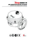
8 Both actuatorsposition the valve plug in response to varyingpneumatic loading pressure on the 2 shows the operation of these size 30-76 and 87 ActuatorsInstruction ManualForm 1203 September 20043 Figure 2. Schematic of Type 667 and 667-4 ActuatorsSTEMSEALSTEMAIR LIFTSSTEM UPSPRING PUSHESSTEM DOWNA6759/ILA Type 667 or 667-4 Actuator can be furnished witheither a top-mounted or a side-mounted handwheelassembly. A top-mounted handwheel assembly isnormally used as an adjustable down travel stop. (Adown travel stop limits Actuator travel in the downdirection [when the stem is traveling out of theactuator].)
9 Travel in the up direction is when the stemis traveling into the Actuator .) A side-mountedhandwheel assembly is normally used as anauxiliary manual Actuator . The side-mountedhandwheel can also be used as an adjustable up ordown travel stop. Casing-Mounted adjustable up ordown travel stops are also available on this repeated or daily manual operation isexpected, the Actuator should beequipped with a side-mountedhandwheel rather than acasing-mounted travel stop ortop-mounted handwheel. Theside-mounted handwheel is designedfor more frequent use as a to table 1 for Specifications of the Type 667and 667-4 actuators.
10 See the Actuator nameplate forspecific information for your avoid personal injury or damage toequipment that may result in themalfunction of the control valve orloss of control of the process causedby excessive pressure, do not exceedthe Maximum Pressures listed in table1. Refer to the Maximum PressureLimitations section Pressure LimitationsThe casing and Diaphragm of Type 667 actuatorsare pressure operated. This air pressure providesenergy to compress the spring, to stroke theactuator, and to seat the valve. The followingexplanations describe the maximum pressure limitsfor an Actuator .