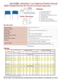
Transcription of Type 944U Polypropylene, DC Link Capacitors - CDE
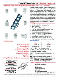
1 DimensionsCDE Cornell Dubilier 1605 E. Rodney French Blvd. New Bedford, MA 02744 Phone: (508)996-8561 Fax: (508)996-3830 Type 944u polypropylene , DC link CapacitorsHigh Current, Low Profi le for Inverter ApplicationsType 944u is specifi cally designed for use in high power DC fi ltering applications. The low inductance internal construction utilizes low loss metallized polypropylene for high ripple current capability. Male or female terminal options off er design fl exibility in a rugged UL 94VO rated fl ame retardant plastic case and resin fi ll.
2 High current ratings and robust mounting fl anges make the 944u suited for inverter applications in electric vehicle power inverters, wind power inverters and motor Low Inductance- Low Profi le- Low ESR- High Ripple Current- High Voltage RatingsSpecifi cationsCapacitance Range33 to 220 FCapacitance Tolerance 10% standardRated Voltage800 to 1400 VdcOperating Temperature Range-40 C to 85 CMaximum rms Current74A @ 55 CMaximum rms Voltage230 VacTest Voltage between Terminal @ 25 C150% rated DC voltage for 10 sTest Voltage between Terminals & Case @ 25 C4 kVac @ 50/60 Hz for 60 sLife Test5000 h @ 85 C.
3 Rated voltageRoHS Compliant H mm 5 mm 6 mm 20 mm mm 45 1 mm 101 mm mm 15 mm M8 x Nm Max TorqueM5 x Nm Max Torque 15 mm mm3 Nm Mounting Torque 90 ThreadedInsertThreadedStudConstruction DetailsCase MaterialPlastic UL94V-0 Resin MaterialDry Resin UL94V-0 Terminal MaterialTin Plated Brass UL Recognized E128034construction only - unprotectedFilmCDE Cornell Dubilier 1605 E. Rodney French Blvd. New Bedford, MA 02744 Phone: (508)996-8561 Fax: (508)996-3830 RatingsTypical Performance Curves944U101K801 AAMTypeCapacitanceToleranceVoltageDiamet er D (mm)Height H (mm)Terminal944U101 = 100 FK = 10%801 = 800 VdcA = = 40M = M8 Thd Stud700 = 70 F102 = 1000 VdcB = 51I = M5 Thd Insert 470 = 47 F122 = 1200 VdcC = 64142 = 1400 VdcCatalogPart NumberCap( F)Rated Voltage(Vdc)HHeightmmTypical ESR 10kHz(m )TypicalESL(nH)Max Irms55 C(A)Thermal Resistance cc( C/W) ca( C/W)944U101K801AA* * * * * * * * * * * * * M = M8 Stud I = M5 InsertPart Numbering (m )Frequency (Hz)
4 160 F 800 Vdc ESR vs Frequency and Temperature85 C65 C45 C25 C0 C-20 C-40 Ripple Current (A)Frequency (Hz)160 F 800 Vdc Rated Ripple Current, Still Air, 5 kh Life45 C55 C65 C75 C85 CType 944u polypropylene , DC link CapacitorsHigh Current, Low Profile for Inverter ApplicationsNOTE: Other ratings, sizes and performance specifications are available. Contact Cornell Dubilier 1605 E. Rodney French Blvd. New Bedford, MA 02744 Phone: (508)996-8561 Fax: (508)996-3830 Expected Lifetime Predictions Expected Lifetime vs Hot Spot Temperature and Applied DC Lifetime (h)Va / Vr50 C60 C70 C85 CType 944u polypropylene , DC link CapacitorsHigh Current, Low Profile for Inverter Applications C ( F)ESR (m )f (kHz) I (Arms)TA ( C)TC ( C) ( C/W) CA ( C/W) CC ( C/W) v (m/s)VA (VDC)VR (VDC)Determine ESR at Operating FrequencyUse the 10 kHz ESR from the ratings operation below 10 kHz, the ESR will need to be adjusted using the following equation: ESR - (10C) + (fC).
5 Determine Thermal Resistance at Operating Frequency and Air FlowCompute = CC + CA. In the ratings tables, CA is for still air. For v = 0 to 5 m/s, multiply CA by [(5 + ( )) / (5 + (v + ) )]Determine Expected LifetimeLook up Expected Lifetime on the graph using VA/VR and TC = TA + I2 (ESR/1000) The maximum allowed temperature rise is 40 C and the maximum allowed core temperature is 95 :Equivalent Series Resistance:Frequency:Ripple Current:Ambient Temperature:Core Temperature:Total Thermal Resistance:Thermal Resistance case-to-ambient:Thermal Resistance core-to-case:Airflow Speed:Applied Voltage:Rated Voltage: FilmNotice and Disclaimer.
6 All product drawings, descriptions, specifications, statements, information and data (collectively, the Information ) in this datasheet or other publication are subject to change. The customer is responsible for checking, confirming and verifying the extent to which the Information con-tained in this datasheet or other publication is applicable to an order at the time the order is placed. All Information given herein is believed to be accurate and reliable, but it is presented without any guaran-tee, warranty, representation or responsibility of any kind, expressed or implied.
7 Statements of suitability for certain applications are based on the knowledge that the Cornell Dubilier company providing such statements ( Cornell Dubilier ) has of operating conditions that such Cornell Dubilier company regards as typical for such applications, but are not intended to constitute any guarantee, warranty or representa-tion regarding any such matter and Cornell Dubilier specifically and expressly disclaims any guarantee, warranty or representation concerning the suitability for a specific customer application, use, storage, transportation, or operating environment.
8 The Information is intended for use only by customers who have the requisite experience and capability to determine the correct products for their application. Any technical advice inferred from this Information or otherwise provided by Cornell Dubilier with reference to the use of any Cornell Dubilier products is given gratis (unless otherwise specified by Cornell Dubilier), and Cornell Dubilier assumes no obligation or liability for the advice given or results obtained. Although Cornell Dubilier strives to apply the most stringent quality and safety standards regarding the design and manufacturing of its products, in light of the current state of the art, isolated component failures may still occur.
9 Accordingly, customer applications which require a high degree of reliability or safety should employ suitable designs or other safeguards (such as installation of protective circuitry or redundancies or other appropriate protective measures) in order to ensure that the failure of an electrical component does not result in a risk of personal injury or property damage. Although all product-related warnings, cautions and notes must be observed, the customer should not assume that all safety measures are indi-cated in such warnings, cautions and notes, or that other safety measures may not be