Transcription of Type MR105 Direct-Operated Pressure Reducing Regulators
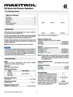
1 Instruction Manual D103246X012 Type MR105 . August 2019. Type MR105 Direct-Operated Pressure Reducing Regulators Contents 2. 2. Principle of 3. 4. Overpressure 8. 8. 9. 9. 10. Parts 16. ! WARNING. Failure to follow these instructions or to properly install and maintain this equipment could result in an explosion, fire and/or chemical contamination P1204. causing property damage and personal TYPE MR105 WITH. HIGH- Pressure ACTUATOR. injury or death. Fisher Regulators must be installed, operated and maintained P1205. in accordance with federal, state and TYPE MR105 WITH. local codes, rules and regulations LOW- Pressure ACTUATOR. and Emerson Process Management Regulator Technologies, Inc. Figure 1. Type MR105 Direct-Operated Pressure (Emerson) instructions. Reducing Regulators If the regulator vents gas or a leak develops in the system, service to the unit may be required. Failure to correct trouble adjustment and unsafe operation.
2 Either could result in a hazardous condition. condition may result in equipment damage Installation, operation and maintenance or personal injury. Call a qualified procedures performed by unqualified personnel when installing, operating and personnel may result in improper maintaining the Type MR105 regulator. Type MR105 . Specifications The Specifications section on this page provides the ratings and other specifications for the Type MR105 . The following information is stamped on the nameplate fastened on the regulator at the factory: type; body size;. maximum inlet, outlet and differential Pressure ; maximum Pressure above setpoint; maximum casing Pressure ;. maximum temperature; spring range; cage type; and trim and diaphragm material. Body Sizes and End Connection Styles Pressure Registration See Table 1 External Shutoff Classification Per ANSI/FCI 70-3-2004 Downstream Control Line Connection Size Class VI (Soft Seat) 1/2 NPT.
3 Maximum Inlet, Outlet and Emergency Spring Case Vent Casing Pressures(1) Type Y602-12. See Table 3 Pressure -Loaded Spring Case Vent(5). Outlet Pressure Ranges(1) 1/2 NPT. 5 to 300 psig / to bar; see Table 2 Approximate Weights Maximum Setpoint(1) For Type MR105 with Low- Pressure Actuator Low- Pressure Actuator: 43 psig / bar NPS 1 / DN 25 : 86 lbs / 39 kg High- Pressure Actuator: NPS 2 / DN 50: 116 lbs / 53 kg Nitrile (NBR) and Ethylene Propylene (EPDM) NPS 3 / DN 80: 165 lbs / 75 kg Diaphragm: 300 psig / bar NPS 4 / DN 100: 174 lbs / 79 kg Fluorocarbon (FKM) Diaphragm: 150 psig / For Type MR105 with High- Pressure Actuator bar NPS 1 / DN 25: 76 lbs / 34 kg Maximum Pressure Over Setpoint to Avoid Internal NPS 2 / DN 50: 105 lbs / 48 kg Parts Damage(1) NPS 3 / DN 80: 155 lbs / 70 kg Low- Pressure Actuator: 20 psig / bar NPS 4 / DN 100: 164 lbs / 74 kg High- Pressure Actuator: 120 psig / bar Options Maximum Differential Pressures(1) Visual Travel Indicator See Table 4 Drain Valve Temperature Capabilities(1)(4) Pressure -Loaded Actuator(5).
4 Nitrile (NBR): -20 to 180 F / -29 to 82 C NACE Construction Fluorocarbon (FKM)(2): 20 to 250 F / -7 to 121 C Bleed Valve (for High- Pressure Actuator Only). EPDM(3): -20 to 225 F / EPDM Elastomer Trim Parts -29 to 107 C. Flow and Sizing Coefficients See Table 5. 1. The Pressure /temperature limits in this Instruction Manual and any applicable standard or code limitation should not be exceeded. 2. Fluorocarbon (FKM) is limited to 200 F / 93 C in hot water. 3. EPDM is limited to 20 to 250 F / -7 to 121 C when used with Low Pressure Actuator. 4. Special low temperature constructions for process temperatures between -76 to 104 F / -60 to 40 C are available by request. The low temperature construction passed Emerson laboratory testing for lockup and external leakage down to -76 F / -60 C. 5. Consult the local Sales Office for this option. ! WARNING Introduction To avoid possible personal injury, Scope of the Manual equipment damage or leakage due to escaping fluid do not stand on or apply This instruction manual provides installation, an external load to the actuator or any adjustment, maintenance and parts ordering part of the regulator while working information for Type MR105 Direct-Operated around the regulator.
5 Pressure Reducing Regulators . Note Description To avoid cavitation, it is recommended that The Type MR105 Direct-Operated Pressure Reducing the customer follow the capacity sizing Regulators are high capacity multi-purpose Regulators . guidelines found in Bulletin : MR105 . They are designed to handle pressures up to 400 psig /. bar and temperatures up to 250 F / 121 C. Large 2. Type MR105 . Table 1. Body Size and End Connection Style END CONNECTION STYLE. BODY MATERIAL Body Size NPS 1 and 2 / DN 25 and 50 NPS 3 and 4 / DN 80 and 100. Cast Iron NPT, CL125 FF or CL250 RF CL125 FF or CL250 RF. NPT, CL150 RF, CL300 RF, CL600 RF CL150 RF, CL300 RF, CL600 RF. WCC Steel(1)(2). or PN 16/25/40 RF or PN 16 RF. NPT, CL150 RF, CL300 RF, CL600 RF CL150 RF, CL300 RF, CL600 RF. CF8M Stainless Steel(1)(2). or PN 16/25/40 RF or PN 16 RF. NPT, CL150 RF, CL300 RF, CL600 RF CL150 RF, CL300 RF, CL600 RF. CF3M Stainless Steel(1)(2).
6 Or PN 16/25/40 RF or PN 16 RF. 1. Optional NACE construction available. 2. Constructions meet API 614 requirements. Table 2. Outlet Pressure Range NPS 1 AND 2 / DN 25 AND 50 BODY SIZE. Maximum Pressure Over Spring Range Spring Part Spring Color Spring Wire Diameter Spring Free Length Setpoint to Avoid Internal Actuator Type Parts Damage Number Code psig bar In. mm In. mm psig bar 5 to 12 to GE42909X012 White 10 to 24 to GE42910X012 Silver Low Pressure 20 14 to 32 to GE42911X012 Orange 18 to 43 to GE43002X012 Red 246. 25 to 60(1) to (1) GE42907X012 Green 43 to 100 to GE42909X012 White High Pressure 120 75 to 175(2) to (2) GE42910X012 Silver 110 to 300(2) to (2) GE42911X012 Orange NPS 3 AND 4 / DN 80 AND 100 BODY SIZE. Maximum Pressure Over Spring Range Spring Part Spring Color Spring Wire Diameter Spring Free Length Setpoint to Avoid Internal Actuator Type Parts Damage Number Code psig bar In. mm In.
7 Mm psig bar 5 to 8 to GE42909X012 White 8 to 20 to GE42910X012 Silver Low Pressure 20 12 to 30 to GE42911X012 Orange 18 to 39 to GE43002X012 Red 246. 39 to 72 to GE42909X012 White High Pressure 71 to 175(2) to (2) GE42910X012 Silver 120 110 to 250(2) to (2) GE42911X012 Orange 1. NPS 2 / DN 50 body size spring range is limited to 45 psig / bar. 2. Maximum setpoint is limited to 150 psig / bar for constructions with Fluorocarbon (FKM) diaphragm. multi-purpose Regulators provide fast, simple, reliable and are opened. Operating personnel must economical Pressure control for a number of applications protect themselves from exposure to and are suitable for different flow media such as liquid, air system fluids or equivalent. and gas. In addition, the drain valve option allows you to drain the system without expensive spool pieces saving you time and space. Also, the bleed valve option allows Principle of Operation you to purge the air trapped underneath the diaphragm The Type MR105 is a Direct-Operated Pressure when the high- Pressure regulator is installed in the upright Reducing regulator.
8 Downstream Pressure is registered position. Typical applications include lube oil, cooling externally through a 1/2 NPT control line tapped in the water and natural gas district stations. bonnet (for low- Pressure actuator, see Figure 2) or in the lower diaphragm casing (for high- Pressure actuator, see Figure 3). When downstream demand decreases, ! WARNING the Pressure under the actuator diaphragm increases. This Pressure overcomes the regulator setting (which Escaping process fluid from an open bleed is set by the regulator control spring). Through the valve may result in regulator damage, action of the actuator stem and valve spring, the valve personal injury and property damage. plug moves closer to the seat ring and reduces the To avoid such injury and damage, make flow. When demand downstream increases, Pressure certain the bleed valve (if used) is properly under the actuator diaphragm decreases.
9 Spring force closed after venting air or equivalent. pushes the actuator stem downward, the valve plug Always open bleed valves slowly. These moves away from the seat ring and the flow increases valves contain no packing, so some fluid downstream as the regulator opens in response to the weepage will occur when the valves 3. Type MR105 . VALVE SPRING. VALVE PLUG. CAGE. SEAT RING. TYPE Y602-12 VENT 1/2 NPT CONTROL. LINE CONNECTION. ACTUATOR STEM. ACTUATOR. DIAPHRAGM. TYPE Y602-12 VENT POINTED DOWN. OR 1/2 NPT Pressure -LOADED. SPRING CASE VENT CONTROL SPRING. M1178. INLET Pressure . OUTLET Pressure . ATMOSPHERIC Pressure . Figure 2. Type MR105 with Low- Pressure Actuator Operational Schematic decreased Pressure underneath the diaphragm. The on how to prevent service conditions downward motion of the plug allows flow through the from exceeding those limits. cage into the downstream system. Additionally, physical damage to the Increased downstream Pressure permits the regulator regulator may result in personal injury to close.
10 The combination of valve spring force and or property damage due to escaping of valve plug unbalance provides positive valve plug accumulated gas. To avoid such injury shutoff against the port and upper seals. and damage, install the regulator in a safe location. Installation All vents should be kept open to permit free flow of gas to the atmosphere. Protect openings against entrance of rain, snow, ! WARNING insects or any other foreign material that may plug the vent or vent line. On outdoor Personal injury or system damage installations, point the spring case vent may result if this regulator is installed, downward to allow condensate to drain. without appropriate overpressure protection, where service conditions Under enclosed conditions or indoors, could exceed the limits given in the escaping gas may accumulate and be Specifications section and/or regulator an explosion hazard. In these cases, nameplate.