Transcription of Types of Pumps
1 An Internet Book on Fluid DynamicsTypes of PumpsPumps come in a vast array of shapes and sizes and in a great range of designs. Here we give just a fewexamples of Pumps from a range of different technological contexts. The presentation will generally followa framework of progressively decreasing specific speed,N, and so will begin with high specific speed pumpsfrom applications involving high flow rates and relatively modest head rise. Figure 1 depicts a schematicand a picture of typical axial flow Pumps in which the flow emerges axially from the impeller but dischargeslaterally from the machine.
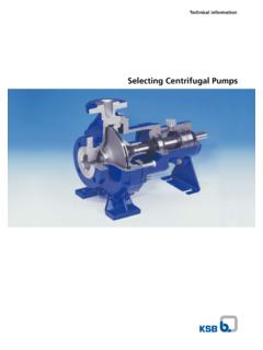
2 Figure 2 shows a mixed flow pump for somewhat lower specific speeds in whichFigure 1: Schematic and picture of typical axial flow 2: Typical mixed flow discharge from the impeller has a radial component so that the head rise has a centrifugal of the impeller the flow returns to an axial direction and proceeds through a stator beforeexiting laterally from the 3 and 4 show a typical centrifugal pump for low specific speeds of orderN= 1 or less. Theflow enters the pump axially (Figure 3), enters the impeller, exits the impeller radially (Figure 4) and isFigure 3: Typical centrifugal 4: Components of a typical centrifugal in a volute (Figure 4) from which it exits in an off-central tangential direction (Figure 3).
3 Atypical centrifugal pump impeller is shown in figure 5 (left). It is a five-bladed impeller made by ByronJackson Pump Division of Borg Warner International Products, has a discharge blade angle of 23 and adesign specific speed,ND, In later sections we present performance data for this impeller testedin combination with several volutes including the single exit, spiral volute shown in Figure 5 (right). Thatvolute was designed to match that impeller in Figure 5 (left).Figure 5: Typical centrifugal pump impeller (left) and volute (right).Figure 6: Typical centrifugal pump vaned a centrifugal pump is equipped with a radial vaned diffuser of the type illustrated in Figure 6.
4 Theflow exits the impeller and proceeds through the vaned diffuser before entering the the design specific speed is below a value of aboutND= , it is necessary to achieve the desiredhead rise by using more than a single centrifugal pump stage. A typical example of such a multistagecentrifugal pump is shown in Figure 7 (left). Apart from the impellers, key components include the vaneddiffusers and the return passages which comprise a 180 bend, a 90 bend and the inward-flowing returnsection. The losses incurred in these return passages constitute a significant contribution to multistagecentrifugal pump performance.
5 As depicted in Figure 7 (right), downhole oil well Pumps represent examplesof multistage centrifugal Pumps and often include 20 or 30 modular stages. Each rotor (impeller) stageis stacked together with a stator (diffuser and return passage) stage, the rotors being keyed to a centralrotating shaft while the stators are keyed to the surrounding 7: Left: Two-plus stages of a multistage centrifugal pump. Right: Cross-section of one and half stages of a multistagedownhole oil well pump showing two return passages or stators and one impeller 8: Two cavitating inducers: on the left a 9 helical inducer; on the right a scale model of the impeller in the SSMElow pressure LOX extensive cavitation cannot be avoided (for example in cryogenic rocket engine Pumps ), it becomesnecessary to alter the pump design so that it can function with substantial cavitation.
6 This is usuallyaccomplished by adding an additional stage ahead to the main impeller, a stage that is commonly called acavitating inducer or just an inducer. The strategy is to handle the incoming flow very gently with smallangle of incidence so that the pressure is gradually increased to a level at which the flow can enter thefollowing impeller without excessive cavitation. As illustrated in Figure 13, cavitating inducers are usuallyhelical with helical angles that involve small initial angles of incidence. Sometimes the discharge flow fromthe inducer is at larger radial positions than the inlet (see Figure 13 (right)) and this adds a significantcentrifugal component to the inducer head rise.
7 Two particular axial flow Pumps or inducers, designed toFigure 9: Left: The liquid oxygen pump in the J2 rocket engine. Right: Scale model of the low pressure liquid oxygen pumpimpeller in the Space Shuttle Main with cavitation, are shown in figure 13, namely a simple 9 helical inducer and a scale model ofthe low pressure liquid oxygen impeller in the Space Shuttle Main Engine (SSME) (see also Figure??).Performance data for both inducers is presented in later 10 and 11 present examples of the rocket engine turbopumps in the Space Shuttle Main Engine(SSME) and in the Ariane V rocket; all are turbopumps, liquid cryogenic Pumps driven by gas turbinespowered by the same gas.
8 The liquid oxygen Pumps necessarily incorporate cavitating inducers; the liquidhydrogen Pumps do not need these additional components. Note that unlike all the other liquid propelledrocket engines, the SSME has two stage pumping systems with both low- and high-pressure Pumps . Earlierfigures (Figure 9 (right)) illustrated the design of the low pressure turbopumps. Figure 10 includes theSSME high pressure liquid hydrogen (top) and liquid oxygen (bottom) Pumps . The high pressure liquidhydrogen pump is a three-stage centrifugal pump while the high pressure liquid oxygen pump is a back-to-back single stage centrifugal pump with a single common the SSME, the Ariane V has just one hydrogen and one oxygen pump as shown in Figure 11.
9 Thehydrogen pump has an inducer followed by two centrifugal stages while the oxygen pump has an inducerfollowed by a single centrifugal stage.**Turning now to compressors handling compressible gases rather than liquids, the same basic options arerelevant though the increase in the density as the fluid passes through the impeller requires modifiedimpeller geometry. This can be seen in the geometry of the typical centrifugal compressor shown in Figure12 where, in comparison with the liquid machine, the flow passage increases less in cross-sectional area asthe flow proceeds through the impeller (in order to adjust for the increase in fluid density).
10 Figure 10: The high pressure liquid hydrogen (top) and liquid oxygen (bottom) Pumps in the Space Shuttle Main 11: The liquid hydrogen (top) and liquid oxygen (bottom) Pumps in the Ariane V rocket 12: Typical centrifugal compressors such as those in gas turbine engines are multi-stage axial machines with many rotorsand stators decreasing in size as the density increases as illustrated in Figure 13: Typical axial compressor.**There are, of course, other Types of Pumps and compressors, in particular positive displacement pumpswhose advantage is that they deliver a particular flow rate relatively independent of the head rise.