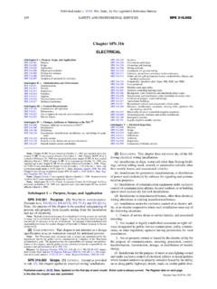
Transcription of Typical Electrical Drawing Symbols and Conventions.
1 1 Typical Electrical Drawing Symbols AND CONVENTIONS Electrical Symbols 2 3 4 5 6 INDICATORS & ALARMS RELAYS 7 ELEMENTARY DIAGRAM CONNECTIONS WIRE NUMBERING 8 9 ABBREVIATIONS ANSI/IEEE Standard Device Numbers 1 - Master Element 2 - Time Delay Starting or Closing Relay 3 - Checking or Interlocking Relay 4 - Master Contactor 5 - Stopping Device 6 - Starting Circuit Breaker 7 Rate of Change Relay 8 - Control Power Disconnecting Device 9 - Reversing Device 10 - Unit Sequence Switch 11 Multifunction Device 12 - Overspeed Device 13 - Synchronous-speed Device 14 - Underspeed Device 15 - Speed - or Frequency-Matching Device 20 - Elect.
2 Operated valve (solenoid valve) 21 - Distance Relay 23 - Temperature Control Device 24 Volts per Hertz Relay 25 - Synchronizing or Synchronism-Check Device 26 - Apparatus Thermal Device 27 - Undervoltage Relay 29 - Isolating Contactor 30 - Annunciator Relay 32 - Directional Power Relay 36 - Polarity or Polarizing Voltage Devices 37 - Undercurrent or Underpower Relay 38 - Bearing Protective Device 39 - Mechanical Conduction Monitor 40 Loss of Field Relay 41 - Field Circuit Breaker 42 - Running Circuit Breaker 43 - Manual Transfer or Selector Device 46 - Reverse-phase or Phase-Balance Relay 47 - Phase-Sequence Voltage Relay 48 - Incomplete-Sequence Relay 49 - Machine or
3 Transformer Thermal Relay 50 - Instantaneous Overcurrent 51 - AC Time Overcurrent Relay 52 - AC Circuit Breaker 53 - Exciter or DC Generator Relay 54 - High-Speed DC Circuit Breaker 55 - Power Factor Relay 56 - Field Application Relay 59 - Overvoltage Relay 60 - Voltage or Current Balance Relay 62 - Time-Delay Stopping or Opening Relay 63 - Pressure Switch 64 - Ground Detector Relay 65 - Governor 66 Notching or jogging device 67 - AC Directional Overcurrent Relay 68 - Blocking or out of step Relay 69 - Permissive Control Device 71 - Level Switch 72 - DC Circuit Breaker 74 - Alarm Relay 75 - Position Changing Mechanism 76 - DC Overcurrent Relay 78 - Phase-Angle Measuring or Out-of-Step Relay 79 - AC-Reclosing Relay 81 - Frequency Relay 83 - Automatic Selective Control or Transfer Relay 84 - Operating Mechanism 85 - Carrier or Pilot-Wire Receiver Relay 86 - Lockout Relay 87 - Differential Protective Relay 89 - Line Switch 90 - Regulating Device 91 - Voltage Directional Relay 92 - Voltage and Power Directional Relay 94 - Tripping or Trip-Free Relay B Bus F Field G Ground or generator N Neutral T Transformer Electrical Basics Sample Drawing Index Basics 1 Overall Plant 1-Line Basics 2 kV Bus 1-Line Basics 3 kV Bus 1-Line Basics 4 600 V 1-Line Basics 5 480 V MCC
4 1-Line Basics 6 kV 3-Line Diagram Basics 7 kV 3-Line Diagram Basics 8 AOV Elementary & Block Diagram Basics 9 kV Pump Schematic Basics 10 480 V Pump Schematic Basics 11 MOV Schematic (with Block included) Basics 12 12-/208 VAC Panel Diagram Basics 13 Valve Limit Switch Legend Basics 14 AOV Schematic (with Block included) Basics 15 wiring (or Connection) Diagram Basics 16 wiring (or Connection) Diagram Basics 17 Tray & Conduit Layout Drawing Basics 18 Embedded Conduit Drawing Basics 19 Instrument Loop Diagram Basics - 1 Plant 1-Line Basics - 2 kV One-Line Basics - 3 kV One-Line Basics - 4 600 V One-Line Basics - 5 MCC One-Line Basics - 6 Three-Line Basics - 7 Three-Line Basics - 8 MOV Block Diagram Basics - 8 MOV Elementary Diagram Basics - 9 Pump Schematic Basics - 10 480 V Pump Block Diagram Basics - 10 480 V Pump Schematic Basics - 11 MOV Schematic Basics - 12 AC Panel Diagram Basics - 13 Valve Limit Switch Legend Basics - 14 AOV Schematic
5 Basics - 15 wiring Diagram Basics - 16 wiring Diagram Basics - 17 Tray & Conduit Layout Basics - 18 Embedded Conduit Layout Basics - 19 Instrument Loop Diagram