Transcription of Typical Roof Truss Design Spans
1 05425 Cold-Formed Steel TrussesRoof Truss SpansEvery TrusSteel roof Truss is a custom Design based upon the unique load, span , bearing, use, and code criteria of a particular project. The load / span tables shown below demonstrate only a tiny subset of the possible combinations available with TrusSteel CFS roof roof Truss Design SpansGeneral Notes:1) Spans shown in charts are in )Loads shown above are outlined as Top Chord Live Load (TCLL), Top Chord Dead Load (TCDL), and Bottom Chord Dead Load (BCDL).3)Top chord designed assuming structural sheathing offers lateral )Bottom chords designed assuming lateral restraint spaced at 24 inches on )Deflection limits: Live Load - L/360 Total Load - L/2406)Trusses designed with ASCE7-98 wind- Wind speed shown in charts- Exposure C- Building category II- Truss bearing elevation is 8 0 - No topographic effect from escarpment or hill taken into account- Enclosed building7)Some trusses above may require a piggyback Truss due to excessive Truss )80+ as shown above means that a span in excess of 80 0 is possible.
2 Refer to TrusSteel Technical Bulletin TB991102 and a TrusSteel engineer regarding these )Scissor trusses designed with a bottom chord pitch equal to half of the top chord pitch a 6/12 top chord pitch scissor Truss will havea 3/12 bottom chord )Designs may include multiple gauges for top and bottom chords as determined by the designer using Alpine s VIEW engineering software. Maximum chord gauges are 18 gauge for the chord and 16 gauge for the )The Truss web pattern used in the Design is to be determined by the designer using Alpine s VIEW engineering 1 Load 2 Load 3 Load 420, 10, 10 psf30, 10, 10 psf20, 10, 10 psf30, 10, 10 psf90 mph wind90 mph wind140 mph wind140 mph windChord Truss Spans2 4 2 4 2 4 2 4 2 4 2 4 2 4 2 4 CommonPitch3/12482680+62382080+52482680+ 62382080+524/12563180+77452380+60563180+ 77452380+605/12623380+80+522780+65623380 +80+522780+656/12643680+80+552780+756433 80+80+552780+757/12643780+80+562880+80+6 43580+80+562880+80+8/12643880+80+583080+ 80+643780+80+583080+80+ScissorPitch3/122 71557322213482627155732221348264/1234196 9432815653634196943281565365/12402277513 318694240227751331869426/124625795738207 24746257957382072477/12502880+6044237353 502880+60442373538/12533180+614925745553 3180+6149257455
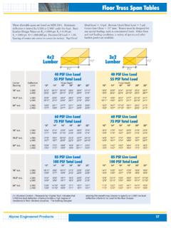
3 MonoPitch3/12362580+60322180+50362580+60 322180+504/12342680+64322380+52342680+64 322380+525/12342680+64322380+52342680+64 322380+526/12342680+64322380+52342680+64 322380+527/12342880+64332380+52342880+64 332380+528/12342880+64332380+52342880+64 332380+52 FlatDepth12 2218242019162420221824201916242018 3023362829213327302336282921332724 3928453535254232392845353525423236 4935644644285941493564464428594148 5836755551297049583675555129704960 653680+6257298055653680+625729805572 663380+68512580+61663380+68512580+61 ALPINED ivision of Alpine Engineered Products, Inc. TrusSteel Division of Alpine Engineered Products, Fisher Court Arlington, TX 76001 888-565-9181 Fax: 817-483-15210211 5K05425 Cold-Formed Steel TrussesFloor Truss SpansEvery TrusSteel floor Truss is a custom Design based upon the unique load, span , bearing, use, and code criteria of a particular project.
4 The load / span tables shown below demonstrate only a tiny subset of the possible combinations available with TrusSteel CFS floor Floor Truss Design SpansLoad 1 Load 240, 10, 5 psf80, 10, 5 psfChord Truss Spacing12 16 24 12 16 24 12 16 24 12 16 24 Depth12 2220181724242220171514132118181614 2522211928272523191716152421201816 2825232132312825221918172724222018 3127262336343129242120182926242220 3330282640373431262322203229272422 3632302744393734282523223431292624 38343229474239363027252337333128 Load 3125, 10, 5 psfChord Truss Spacing12 16 24 12 16 24 Depth12 141312111716141314 161414132018171516 181615142220191718 201817152522211920 221918162724222122 232120182926242224 2522211831282624 General Notes:1) Spans Shown in charts are in )Loads shown above are outlined as Top Chord Live Load (TCLL), Top Chord Dead Load (TCDL), and Bottom Chord Dead Load (BCDL).
5 3)Top and bottom chords designed assumingstructural sheathing offers lateral )Deflection limits:Live Load - L/480 Total Load - L/3605)Chases are to be located in center of chase width allowed is 24 )Refer to TrusSteel Technical Bulletin TB971125 for TrusSteel floor Truss Design )Designs may include multiple gauges for top and bottom chords as determined by the designer using Alpine s VIEW engineering software. Maximum chord gauges are 18 gauge for the chord and 16 gauge for the Duct Opening Sizes for Chord Size Steel Floor TrussDepthPanel SizeABCDEF12 Duct Opening Sizes for Chord Size Floor TrussDepthPanel SizeABCDEF12 SizeDepthAllowable Duct SizesALPINED ivision of Alpine Engineered Products, Inc. TrusSteel Division of Alpine Engineered Products, Fisher Court Arlington, TX 76001 888-565-9181 Fax: 817-483-1521 All panel and duct opening size dimensions shown above are in inches.