Transcription of Typical Tolerances of Manufacturing Processes - …
1 EML 2322L MAE Design and Manufacturing Laboratory Typical Tolerances of Manufacturing Processes In the past, one of the traditional weaknesses with graduating mechanical design engineers is their inability to select Tolerances . Most students were reasonably proficient using one or more CAD packages and could produce drawings which were pretty good (given their limited experience levels). However, despite knowing how to put a tolerance on a drawing, most students generally had no idea what the actual numbers should be, or any sense of what the process for selecting reasonable Tolerances might consist of. Since Geometric Dimensioning and Tolerancing (GD&T) is in widespread use in industry, the MAE curriculum has changed to include it in EML2023. Nevertheless, knowing how to properly express a tolerance for cylindricity or parallelism between two surfaces on a part drawing is not the same thing as knowing what a reasonable number for that tolerance should be.
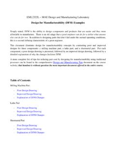
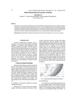
2 After taking EML2322L, the students should be much more proficient in these areas. To facilitate the students understanding of this important area of mechanical design, we have put together a few slides on some common Manufacturing Processes , and what their tolerance producing capability is. After taking EML2322L, the students should have a tangible understanding of the Tolerances associated with basic Manufacturing Processes used in this course ( milling, turning, drilling, reaming, bandsaw cutting, etc.) Process Tolerances Process tolerance vs. Feature Size Surface Finish vs. Production Time FIGURE Surface finish produced by various Processes . (Source: Wikipedia) Figure presents a collection of the most common Manufacturing Processes and the Tolerances commonly associated with each of them. As explained in the legend, the shaded portions of the bars represent the average application of these Processes and mean virtually any Manufacturing shop should be able to achieve these Tolerances .
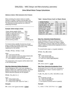
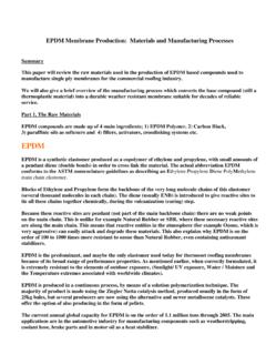
3 The remaining portion of the bar indicates the less frequent application, which means one of two things: (1) highly skilled operators and equipment in excellent condition are required to obtain the Tolerances on the higher precision end of the range or (2) the process can easily achieve the Tolerances on the lower precision end of the range, but a cheaper alternative likely exists, which could significantly reduce part cost. Figure presents another collection of the most common Manufacturing Processes and common Tolerances associated with them as a function of Typical part size. The important point to take away from this figure is the general trend showing Typical achievable part Tolerances grow as a function of parts size. In other words, the ability to achieve a certain tolerance is a function of part size. As an example, let s use a pair of the 6 measuring calipers found in lab. Do these calipers measure the size of a feature perfectly?
4 No, they do not, as nothing can. However, they do an adequate job for the Tolerances we try to hold on the parts we produce. To quantify this point, these calipers have an error associated with them of approximately per one inch of measurement. That means if we measure a 1 part dimension, that measurement is really . This is not a big deal to us because we often use a tolerance of on features that need to be accurately located. But what happens when we use a measuring instrument of similar accuracy to check a part that is 10 in length? Now our measurement is really . So if we still require this part to be within the tolerance , it should be obvious we now have a serious problem. The same problem exists with digital calipers, digital read outs on machine tools, and position feedback encoders on CNC machines. All measuring instruments have a positioning error associated with them that is linearly compounded over larger travels.
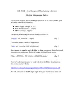
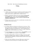
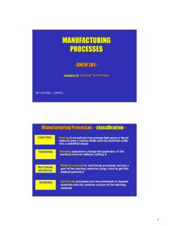
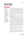
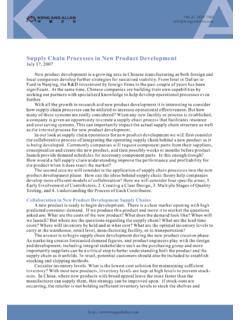
5 Figure shows relative production time as a function of surface finish for common Manufacturing Processes . Although the curve for each process is slightly different, the general trend shows that the relative production time increases exponentially as a function of achieved surface finish. In other words, doubling the surface finish requirements translates to more than twice the part cost. Therefore we should always be able to justify the surface finish requirement we list on each surface of the parts we design. Saving ten minutes of machining time on one part surface might not seem like a worthwhile achievement, but remember that pennies make dollars, and the savings can be substantial for a properly designed part. Worded differently, failure to specify the roughest surface finishes permissible on each surface can easily increase part cost by an order of magnitude! Figure presents a collection of the most common Manufacturing Processes and the surface finishes commonly associated with each of them.
6 As explained in the legend, the shaded portions of the bars represent the average application of these Processes and means almost any shop should be able to achieve these finishes. The remaining portion of the bar indicates the less frequent application, which means one of two things: (1) highly skilled operators and equipment in excellent condition are required to obtain the surface finishes on the higher precision end of the range or (2) the process can easily achieve the finishes on the lower precision end of the range, but a cheaper alternative likely exists, which could significantly reduce part cost.