Transcription of U-GAGE Figure 1. Standard Model QT50UVR Series …
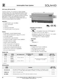
1 DatasheetFigure 1. Standard ModelFigure 2. Teflon-Protected Model Fast, easy-to-use TEACH-Mode programming; no potentiometeradjustments SPDT electromechanical relay for high-capacity switching Universal supply voltage: 85 to 264 V ac / 48 to 250 V dc Rugged encapsulated design for harsh environments Models available with factory-installed Teflon flange and film coatingbonded over the transducer for protection from harsh environments Unique housing design allows for multiple mounting configurations Choose models with integral 2 m ( ft) or 9 m (30 ft) cable, or with Mini-style or Micro-style quick-disconnect fitting Wide operating range of 20 C to 70 C ( 4 F to 158 F)
2 Temperature compensationTeflon is a registered trademark of Dupont Information about dc-voltage models is available on Banner s website: : Not To Be Used for Personnel ProtectionNever use this device as a sensing device for personnel protection. Doing so could lead toserious injury or death. This device does not include the self-checking redundant circuitry necessaryto allow its use in personnel safety applications. A sensor failure or malfunction can cause either anenergized or de-energized sensor output RangeCable 1 Operation ModelQT50 UVR3W200 mm to 8 m (8 in to 26 ft)5-wire, 2 m ( ft) cableWindow-limit ( )QT50 UVR3WQ15-pin Micro-style Quick Disconnect (QD )QT50 UVR3WQ5-pin Mini-style QDQT50 UVR3F5-wire, 2 m ( ft) cableFill-level control (pump-in and pumpout)
3 QT50 UVR3FQ15-pin Micro-style QDQT50 UVR3FQ5-pin Mini-style QDOverviewUltrasonic sensors excel in position-monitoring applications and in applications involving clear or multi-colored sensors are available in a variety of models: dc sensors with either analog or two discrete outputs, or universalvoltage models that feature an SPDT electromechanical relay for switching larger loads. Programming and setup for theuniversal voltage models are accomplished using the sensor s two push are available with Teflon sensor face and hex nut, plus Teflon-coated transducer and special o-rings for use inharsh environments, such as fill-level monitoring in an acidfilled order the 9 m cable models, add the suffix W/30 to the Model number of a cabled sensor (for example, QT50 UVR3W w/30).
4 Models with aQD connector require a mating QT50 UVR Series Sensors Original Document117764 Rev. G15 September 2016117764 Principles of OperationUltrasonic sensors emit one or multiple pulses of ultrasonic energy, which travel through the air at the speed of sound. Aportion of this energy reflects off the target and travels back to the sensor. The sensor measures the total time requiredfor the energy to reach the target and return to the sensor. The distance to the object is then calculated using thefollowing formula: D = ct 2D = distance from the sensor to the targetc = speed of sound in airt = transit time for the ultrasonic pulseTo improve accuracy, an ultrasonic sensor may average the results of several pulses before outputting a new EffectsThe speed of sound is dependent upon the composition, pressure and temperature of the gas in which it is traveling.
5 Formost ultrasonic applications, the composition and pressure of the gas are relatively fixed, while the temperature air, the speed of sound varies with temperature according to the following approximation:In metricunits:Cm/s = 20 273 + TC In English units: ft/s = 49 460 + TFCCm/s = speed of sound in meters per secondCft/s = speed of sound in feet per secondTC = temperature in CTF = temperature in FTemperature CompensationThe speed of sound changes roughly 1% per 6 C (10 F). QT50U Series ultrasonic sensors have temperaturecompensation available; temperature compensation will reduce the error due to temperature by about 90%.
6 Changes in air temperature affect the speed of sound, which in turn affects the distance reading measured by the increase in air temperature shifts both sensing window limits farther away from the sensor. Conversely, a decrease inair temperature shifts both limits closer to the sensor. This shift is approximately of the limit distance for a 20 Cchange in temperature. With temperature compensation enabled, the sensor will maintain the window limits to over the entire -20 to +70 C ( 4 to +158 F) : If temperature compensation is enabled, exposure to direct sunlight can affect the sensor sability to accurately compensate for changes in If the sensor is measuring across a temperature gradient, the compensation will be lesseffective.
7 With temperature compensation enabled, the temperature warmup drift upon power-up is lessthan of the sensing distance. After 30 minutes, the apparent switchpoint will be of the actual position. After 60 minutes, the apparent switchpoint will be within ofthe actual sensor can be configured for one of three output response times and to enable or disable temperature are accomplished using the sensor s Speed push button, using the procedures described below. A button click isdefined as: Click Select the output response the Speed button until the desired output response time LED cycles throughSolid Red, Solid Amber, and OFFto indicate selected Output Response Time.
8 Solid Red Slow Response (1600 ms) Solid Amber Medium Response (400 ms) (factorydefault) OFF Fast Response (100 ms)No further action required; sensor stores selection and remains inRUN Enable or disable the temperature compensation. U-GAGE QT50 UVR Series - Tel: +1-763-544-3164P/N 117764 Rev. GActionResultPush and hold the Speed push button for 10 seconds to enterprogramming LED flashes: Flashing Amber Temperature Compensation isenabled (default). Flashing Red Temperature Compensation is the Speed button to toggle between enable and LED flashes: Flashing Amber Temperature Compensation isenabled (default).
9 Flashing Red Temperature Compensation is and hold the Speed button for 10 seconds to return to Runmode. Sensor stores selection. Sensor returns to Run mode. Response LED returns to a solid color or OFF to indicatecurrent Output Response Time ModelsQD ModelsNormally Open/Pump-InNormally Open/Pump-InKey Load4513285-264 V ac, 50/60 Hz48-250 V dc**shield*Output Current 8 A Max. 45132shield*Output Current (4 A or 8 A Max.)**Load85-264 V ac, 50/60 Hz 48-250 V dc** 1 - brown2 - white3 - blue4 - black5 - yellowNormally Closed/Pump-OutNormally Closed/Pump-OutKey 45132shield*Output Current 8 A V ac, 50/60 Hz 48-250 V dc** 45132shield*LoadOutput Current (4 A or 8 A Max.)
10 **85-264 V ac, 50/60 Hz 48-250 V dc** 1 - brown2 - white3 - blue4 - black5 - yellow* Banner recommends that the shield wire be connected to earth ground.** DC wiring is without regard to polarity** 4 A maximum for sensors with Micro-style quick disconnects; 8 A maximum for sensors with Mini-style IndicatorsPower ON/OFF LED (Green) ON when sensor power is LED (Red) indicates incoming signal strength and LED StatusIndicatesON BrightGood signalON DimMarginal signal strengthOFFNo signal is received 2 or target is beyond the sensor's range limitationsOutput LED (Amber or Red) indicates the target position relative to the window limits, or TEACH mode QT50 UVR Series Sensors P/N 117764 Rev.