Transcription of U.S. TSUBAKI ENGINEERING CHAIN DIVISION ENGINEERING …
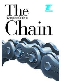
1 A-iiiA ENGINEERING class TSUBAKIENGINEERING CHAIN DIVISIONENGINEERING class CHAINSC ontentsPageDRIVE CHAINS A-1 ~ A-16 INTRODUCTIONA-1 ~ A-2 DRIVE CHAIN SPECIFICATIONSA-3 ~ A-4 DRIVE CHAIN SELECTION GUIDELINESA-5 ~ A-16 ROLLER CONVEYOR CHAINSA-17 ~ A-52 INTRODUCTIONA-17 ~ A-18 ROLLER CONVEYOR CHAIN SPECIFICATIONSA-19 ~ A-20 ROLLER CONVEYOR CHAIN ATTACHMENTSA-21 ~ A-34 APRON CONVEYORS A-35 ~ A-42 ROLLER CONVEYOR CHAIN SELECTION GUIDELINESA-43 ~ A-52 STEEL BUSHED CHAINSA-53 ~ A-60 INTRODUCTION AND SPECIFICATIONSA-53 ~ A-54 ATTACHMENTSA-55 ~ A-60 CAST COMBINATION CHAINSA-61 ~ A-64 INTRODUCTIONA-61 ~ A-62 SPECIFICATIONS AND ATTACHMENTS A-63 ~ A-64 WELDED STEEL CHAINSA-65 ~ A-74 INTRODUCTIONA-65 WELDED STEEL MILL CHAIN AND ATTACHMENTSA-66 ~ A-72 WELDED STEEL DRAG CHAIN AND ATTACHMENTSA-73 ~ A-74 DROP FORGED RIVETLESS CHAINSA-75 ~ A-82 INTRODUCTION AND SPECIFICATIONSA-75 ~ A-76 ULTRA WEAR LIFE CHAINSA-77 BARLOOP CHAINSA-78 ATTACHMENTS AND SPROCKETSA-79 ~ A-80 CATERPILLAR DRIVE CHAINSA-81 ~ A-82 BAR AND PIN CHAINSA-83 ~ A-86 INTRODUCTIONA-83 DRAW BENCH CHAINSA-84 DOUBLE FLEX CHAINSA-85 ~ A-86 SPECIALTY CHAINS A-87 ~ A-114 INTRODUCTIONA-87 ~ A-88RF CONVEYOR CHAIN BASIC METRIC SERIESA-89 ~ A-92 FLOW CONVEYOR CHAINSA-93 ~ A-98 FOR FC TYPE HORIZONTAL FLOW CONVEYORA-93 ~ A-94 FOR LC TYPE INCLINED FLOW CONVEYORA-95 FOR FK TYPE FLOW CONVEYOR FOR GRAINA-96NF BLOCK CHAIN FOR FLOW CONVEYORA-97 ~ A-98 OUTBOARD ROLLER CONVEYOR CHAINSA-99 RFD DEEP LINK CHAINSA-100 SANITATION CHAINSA-101 ~ A-102 ACR 810 COLLECTOR TANK CHAINSA-103 ~ A-104 JAC TYPE BAR SCREEN CHAINSA-105 ~ A-106 ACS TYPE HEAVY DUTY COLLECTOR CHAINSA-107 ~ A-108 BEARING ROLLER CONVEYOR CHAINSA-109 ~ A-110 LARGE SIZE STEEL DOUBLE PLUS CHAINSA-111 ~ A-112 BEARING BUSH CHAINSA-113 ~ A-114 UNION CHAIN DIVISION - DRIVE CHAINSA-1 Drive ChainsENGINEERING class DRIVE CHAINKeep Your Operation Moving with Union ChainUnion Drive Chains are designed to exceed the listed ultimatestrength ratings.
2 These ratings are very significant. Chains withgreater ultimate strength have higher actual yield and greaterfatigue strength. With Union chains, you get extra reservestrength to withstand high shock Manufacturing Means Greater Fatigue StrengthUnion ENGINEERING class Drive Chains are built to withstand the most rugged conditions. We use the latest manufacturing and heat-treating techniques to manufacture every component is carefully machined to close tolerances toensure precise pitch control for smooth sprocket/ CHAIN interac-tion. That means longer service life for CHAIN and the Power of AlloyWhen parts require extra hardness, we use alloy steel to makethe components. This provides more uniform core strength,which is particularly important for heavy duty Union Drive CHAIN with an ultimate strength rating higherthan 112,000 pounds is made entirely of alloy steel. All UnionDrive Chains are furnished with alloy steel pins. Reduce Maintenance Costs and DowntimeUnion Drive Chains stand up to the toughest environments forhour after hour of uninterrupted service.
3 Optimum strength Fatigue resistant Pre-tested Alloy steel parts Press fit construction Accurate pitch controlYour equipment is on the line. Count on Union ENGINEERING class CHAINSA-2 Quality ComponentsHigh-Strength Sidebars Sidebars for Union Drive Chains with an ultimate strength rating higher than 112,000 pounds are manufactured from alloy steel and are through-hardened. This adds strength andextends the service life of the CHAIN . In addition, our advancedmanufacturing techniques ensure accurate hole size and pre-cise pitch control, distributing the load equally and providingsmooth sprocket Machined BushingsBushings for Drive CHAIN are precision machined to providesmooth bearing surfaces that means less resistance are through-hardened or case hardened to meet yourapplication. The result is smooth riding bushings that Steel Induction Hardened PinsAll Drive CHAIN pins are made from alloy steel and are through-hardened for toughness and strength. In addition,chains designed for heavy duty power shovel applications have ground bearing surfaces and full round induction harden-ing.
4 This provides the best combination of high yield strengthand superior wear RollersOur rollers are made from a high quality material for use when critical tolerances and superior finish are required. Thenthey are through-hardened to withstand high shock loads. Forchains with high ultimate strength ratings, rollers are typicallymade from alloy steel. A ENGINEERING class CHAINSUNION CHAIN DIVISION - DRIVE CHAINSA-3A ENGINEERING class CHAINSETDGCBHP itchPitchTEDGCBHP itchPitchDrive Chainstraight sidebar styleoffset sidebar styleA-4To locate compatible sprockets for your CHAIN , refer to the Product Cross-Reference in Section : Dimensions are subject to change. Contact Union CHAIN to obtain certified prints for design and ENGINEERING class CHAINSBCEGDHTUS-2065 K AHTRO-3140 K AHTRO-3160 K AHTRO-3180 K AHTRO-25H K A CHTUS-882 K CHTUS-3011 O 2512 K AHTIHUS-1030 K AHTUS-1031 K AHTUS-3075 K AHTUS-3514 O 2814 K AHTUS-1241 K AHTIHUS-1242 K AHTIHUS-1245 O 3315 K AHTIHUS-4121 K AHTIHUS-4122 K AHTIHUS-4522 O 3618 K AHTIHUS-5031 O 4020 K AHTIHUS-5035 K AHTIHUS-5542 K AHTIHUS-5738 K AHTIHUS-6042 O 4824 K AHTIHUS-6066 K AHTIHUS-64S
5 K AHT344 SXX K AHTIHUS-4031 K AHTIHUS-1353 K AHTIHUS-5042 K AHTIHUS-6566 K AHTIHUS-7080 K .31 AHT .81 .22 AHT .70 .25 AHT .80 .28 AHT .38 AHT .91 .25 CHT .75 .25 CHT .64 .38 AHT .31 .31 CHT .91 .38 AHT .91 .50 AHT .50 CHT .50 AHT .56 AHT .56 AHT .56 AHT .56 AHT .63 AHT .75 AHT .75 AHT .69 AHT .75 AHT AHT .75 AHT .38 AHT .56 AHT .63 AHT .63 AHT .75 AHT .88 AHT .88 AHT AHTD rive CHAIN SpecificationsAll dimensions are in inches unless otherwise 65,000 4, 52,800 2, 67,300 3, 80,000 4, 87,000 4, 25,000 2, 26,000 2, 110,000 6,100 28,000 4, 48,000 4, 75,000 5, 140,000 7,700 112,000 9,000 140,000 9,000 170,000 10,100 210,000 10,700 210,000 10,700 220,000 12,300 310,000 17,500 350,000 19,600 420,000 23,600 380,000 23,000 420,000 23,600 600,000 27,600 125,000 6,900 170,000 10,050 310,000 17,500 210,000 16,000 420,000 23,600 600,000 30,600 800,000 37,150 Head Wdth.
6 Dia. Th. Feet(lbs.) (lbs.)( )Indicates this CHAIN is normally stocked. All others are : O= offset sidebar; S= straight sidebar2 Pin style: K = Full round; A = Double : HC = High carbon; CHT = Carbon heat-treated; AHT = Alloy heat-treated; AHTIH = Alloy heat-treated and induction hardened; CCH = Carbon case hardened;ACH = Alloy case CHAIN DIVISION - DRIVE CHAINSA-5A ENGINEERING class CHAINSLoadLoadLoadLoadApplicationClass1 ApplicationClass1 ApplicationClass1 ApplicationClass1 Table 1 Application Classifications1U = Uniform load; M = Moderate shock; H = Heavy Liquids ..ULiquids and Solids ..MLiquids Variable Density ..MBlowersCentrifugal ..ULobe ..MVane ..UBrewing and DistillingBottling Machinery ..UBrew Kettles Cont. Duty ..UCookers Cont. Duty ..UMash Tubs Cont. Duty ..UScale Hopper, Freq. Starts ..MCan Filling Machines ..UCane Knives ..MCar Dumpers ..HCar Pullers ..MClarifiers ..UClassifiers ..MClay Working MachineryBrick Press.
7 HBriquette Machine ..HClay Working Machinery ..MPub Mill ..MCompressorsCentrifugal ..ULobe ..MReciprocating, Multi-Cylinder ..MReciprocating, Single-Cylinder .HConveyors Uniformly Loaded or FedApron ..UAssembly ..UBelt ..UBucket ..UChain ..UFlight ..UConveyors Uniformly Loaded or Fed (Continued)Oven ..UScrew ..UConveyors Heavy DutyNot Uniformly FedApron ..MAssembly ..MBelt ..MBucket ..MChain ..MFlight ..MLive Roll ..MOven ..MReciprocating ..HScrew ..MShaker ..HCranesMain Hoists ..UBridge Travel ..MTrolley Travel ..MCrusherOre ..HStone ..HSugar ..MDredgesCable Reels ..MConveyors ..MCutter Head Drives ..HJig Drives ..HManeuvering Winches ..MPumps ..MScreen Drive ..HStackers ..MUtility Winches ..MDry Dock CranesMain Hoist, Auxiliary Hoist, Boom (Luffing) ..UDry Dock Cranes (Continued)Rotating (Swing or Slew) ..MTracking (Drive Wheels) ..HElevatorsBucket Uniform Load ..UBucket Heavy Load ..MBucket Cont. Centrifugal Discharge.
8 UEscalators ..UFreight ..MGravity Discharge ..UMan Lifts ..HPassenger ..HFansCentrifugal ..UCooling Towers Induced Draft UCooling Towers Forced Draft .UInduced Draft ..MLarge (Mine, etc.) ..MLarge (Industrial) ..MLight (Small Diameter) ..UFeedersApron ..MBelt ..MDisc ..UReciprocating ..HScrew ..MFood IndustryBeet Slicer ..MCereal Cooker ..UDough Mixer ..MMeat Grinders ..MGenerators (Not Welding) ..UHammer Mills ..HHoistsHeavy Duty ..HMedium Duty ..MSkip Hoist ..MLaundry WashersReversing ..MLaundry Tumblers ..MLine ShaftsDriving Processing Equipment .MLight ..UOther Line Shafts ..ULumber IndustryBarkers Hydraulic, Mechanical ..MBurner Conveyor ..MChain Saw and Drag Saw ..HChain Transfer ..HCraneway Transfer ..HDe-barking Drum ..HEdger Feed ..MGang Feed ..MGreen CHAIN ..MLive Rolls ..HLog Deck ..HLog Haul Incline ..HLog Haul Well Type ..HLog Turning Device ..HMain Log Conveyor ..HOff Bearing Rolls ..MPlaner Feed Chains.
9 MPlaner Floor Chains ..MPlaner Tilting Hoist ..MRe-saw Merry-go-round Conveyor ..MRoll Cases ..HSlab Conveyor ..HSmall Waste Conveyor Belt ..USmall Waste Conveyor CHAIN MSorting Table ..MTipple Hoist Conveyor ..MTipple Hoist Drive ..MTransfer Conveyors ..MStep 1:Determine class of Driven LoadFrom the Application Classifications Table 1 determine the class of the driven load: uniform load, moderate shock, heavy SELECTION PROCEDURESELECTION GUIDELINEST here are two methods to determine the right drive CHAIN foryour application: Standard and Working Load. To determine thesuggested CHAIN , follow Steps 1-10 of the Standard SelectionProcedureon pages A-5 through A-7. An example procedure isshown on page A-15. Each selection procedure is intended to be used for EngineeringClass Drive CHAIN (ASME/ANSI Standard ). A-6A ENGINEERING class CHAINSR equired Information for Drive Selection Type of input horsepower (electric motor, internal combustionengine, etc.). Type of equipment to be driven.
10 Horsepower to be transmitted. Full load speed of the fastest running shaft (RPM). Desired speed of the slow speed shaft (RPM).Note:If speeds are variable, determine maximum and minimum speed and HP to be transmitted at each speed. Diameters of the driving and driven shafts. Center to center distance of :If this dimension is adjustable, determine amount of adjustment. Position of drive and space limitations, if any. Proposed method of lubrication. Conditions of drive. Drives with more than two sprockets,idlers, or unusual conditions such as severely abrasive orcorrosive atmosphere, extremely high or low temperatures,severely fluctuating loads, frequent stops and starts, etc.,require special consideration. It is advisable to consult Unionengineers for selections of this 1 Application Classifications (Continued)1U = Uniform load; M = Moderate shock; H = Heavy Industry (Continued)Transfer Rolls ..MTray Drive ..MTrimmer Feed ..MWaste Conveyor ..MMachine ToolsBending Roll.