Transcription of UDC2500 universal digital controller quick start …
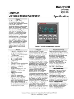
1 51-52-25-124 March 2007 quick start guide for UDC2500 universal digital ControllerFor Limit controller see page 3. For detailed instructions see UDC2500 controller Product Manual 51-52-25-127. Step 1. Model Number Interpretation Write your controller model number in the boxes. Then refer to Tables I, II, and III and circle the corresponding options to identify your controller s features. A dot indicates the feature is available. - - - - X X X X X - X X Key Number Table I Table II Table III Other options KEY NUMBER - UDC2500 Single Loop ControllerSelectionDigital controller for use with 90 to 264 Vac PowerDC2500 digital controller for use with 24 Vac/dc PowerDC2501 TABLE I - Specify Control Output and/or AlarmsDescription_ BOne Alarm Relay Only0 _C _E _None (Can be used as an indicator only)Current Output (4 to 20ma, 0 to 20 ma)Electro Mechanical Relay (5 Amp Form C)
2 Solid State Relay (1 Amp)_ A_ TOutput #2 and Alarm #1 or Alarms 1 and 2_ 0E-M Relay (5 Amp Form C) Plus Alarm 1 (5 Amp Form C Relay)Solid State Relay (1 Amp) Plus Alarm 1 (5 Amp Form C Relay)AvailabilityA _T _R __ EOutput #1 Open Collector transistor outputDual 2 Amp Relays (Both are Form A) (Heat/Cool Applications)No Additional Outputs or AlarmsOpen Collector Plus Alarm 1 (5 Amp Form C Relay) DC2500 2501 TABLE II - Communications and Software SelectionsSelection0 _ _ _1 _ _ _2 _ _ _10 Base-T Ethernet (Modbus RTU) Plus Auxiliary Output/ digital Inputs3 _ _ _ _ 0 _ __ A _ __ B _ __ L _ _aaNo Selection_ _ 0 __ _ _ 0_ _ _ RAvailabilitySoftware SelectionsStandard Functions, Single DisplayDual Display with Auto/ManualSet Point Programming (12 Segments) Dual Display, Auto/ManualLimit ControllerCommunicationsNoneInfrared interfaceInfrared Interface Included (Can be used with a Pocket PC)Auxiliary Output/ digital Inputs (1 Aux and 1 DI or 2 DI)
3 RS-485 Modbus Plus Auxiliary Output/ digital InputsNoneReserved DC2500 2501 TABLE III - Input 1 can be changed in the field using external resistorsSelection1 _2 _3 __ 0_ 1 Input 2 None0-5V, 1-5V, 0-20mA, 4-20mAInput 1TC, RTD, mV, 0-5V, 1-5 VTC, RTD, mV, 0-5V, 1-5V, 0-20mA, 4-20mATC, RTD, mV, 0-5V, 1-5V, 0-20mA, 4-20mA, 0-10 VAvailability Page 1 of 4 Step 2. Dimensions and mounting Max. panel thickness19, ,0 + 0,8-0,003,62 + 0,03-0,0092,0 + 0,8-0,003,62 + 0,03-0,00mminches17,90,70113,14,4590,63, 57108,64,289,00,35 Step 3. Wiring L1L2/N4567892021252627191011121314151618 17 EthernetSHIELD 14 RXD - 15 RXD + 16 TXD - 17 TXD + 18 RTDA larm #1AC/DCLineVoltageEarth GroundHotNeutral+--+-+-+Input #1 Output #1DC mAoutput ++--Open CollectorSolid State RelayInput #2RS48516 SHIELD17 D+ (B)18 D - (A)
4 Linear mAThermocoupleLinear V/mV2ndCurrent Output12 +13 -10 +11 12 +13 Single Relay+-SSRO utput #2/Alarm #2 Open CollectorDual Relay250 ohm222324 digital Input #2 digital Input #121 Single RelayL1L2/N45678920212526271910111213141 5161817 EthernetSHIELD 14 RXD - 15 RXD + 16 TXD - 17 TXD + 18 RTDA larm #1AC/DCLineVoltageEarth GroundHotNeutral+--+-+-+Input #1 Output #1DC mAoutput ++--Open CollectorSolid State RelayInput #2RS48516 SHIELD17 D+ (B)18 D - (A)Linear mAThermocoupleLinear V/mV2ndCurrent Output12 +13 -10 +11 12 +13 Single Relay+-SSRO utput #2/Alarm #2 Open CollectorDual Relay250 ohm250 ohm222324222324 High Level Only L1L2/N4567892021252627191011121314151618 17 EthernetSHIELD 14 RXD - 15 RXD + 16 TXD - 17 TXD + 18 RTDA larm #1AC/DCLineVoltageEarth GroundHotNeutral+--+-+-+Input #1 Output #1DC mAoutput ++--Open CollectorSolid State RelayInput #2RS48516 SHIELD17 D+ (B)18 D - (A)
5 Linear mAThermocoupleLinear V/mV2ndCurrent Output12 +13 -10 +11 12 +13 Single Relay+-SSRO utput #2/Alarm #2 Open CollectorDual Relay250 ohm250 ohm222324222324 digital Input #2 digital Input #121 Single RelayL1L2/N45678920212526271910111213141 5161817 EthernetSHIELD 14 RXD - 15 RXD + 16 TXD - 17 TXD + 18 RTDA larm #1AC/DCLineVoltageEarth GroundHotNeutral+--+-+-+Input #1 Output #1DC mAoutput ++--Open CollectorSolid State RelayInput #2RS48516 SHIELD17 D+ (B)18 D - (A)Linear mAThermocoupleLinear V/mV2ndCurrent Output12 +13 -10 +11 12 +13 Single Relay+-SSRO utput #2/Alarm #2 Open CollectorDual Relay250 ohm250 ohm222324222324 High Level Only Step 4. Configuration Procedure Step Operation Press Result 1 Enter Set Up Mode SetupSetup Upper Display = SET Lower Display = TUNING (This is the first Set Up Group title) 2 Select any Set Up Group SetupSetup Sequentially displays the other Set Up group titles shown in the prompt hierarchy.
6 (See 5. Configuration Record Sheet for prompts.) You can also use the or keys to scan the Set Up groups in both directions. Stop at the Set Up group title that describes the group of parameters you want to configure. Then proceed to the next step. 3 Select a Function Parameter FunctionFunctionFunction Upper Display = the current value or selection for the first function prompt of the selected Set Up group. Lower Display = the first Function prompt within that Set Up group. Sequentially displays the other function prompts of the Set Up group you have selected. Stop at the function prompt that you want to change, then proceed to the next step. 4 Change the Value or Selection or Increments or decrements the value or selection that appears for the selected function prompt.
7 If you change the value or selection of a parameter while in Set Up mode then decide not to enter it, press M-A RESET] once the original value or selection is recalled. 5 Enter the Value or Selection FunctionFunctionFunction Enters value or selection made into memory after another key is pressed. 6 Exit Configuration LowerDisplayLowerDisplayLowerDisplay Exits configuration mode and returns controller to the same state it was in immediately preceding entry into the Set Up mode. It stores any changes you have made. If you do not press any keys for 30 seconds, the controller times out and reverts to the mode and display used prior to entry into Set Up mode. 51-52-25-124 March 2007 quick start guide for UDC2500 universal digital ControllerStep 5.
8 Configuration Record Sheet Enter the value or selection for each prompt on this sheet so you will have a record of how your controller was configured. Group Prompt Function Prompt Value or Selection Factory Setting Group Prompt Function Prompt Value or Selection Factory Setting TUNING PB or GAIN RATE T I MIN or I RPM MANRST PB2 or GAIN 2 RATE2T I2 MIN or I2 RPM CYCT1 or CT1 X3 CYC2T2 or CT2 X3 SECUR LOCK AUTOMA A TUNE RN HLD SP SEL _____ _____ _____ _____ _____ _____ _____ _____ _____ _____ _____ _____ _____ _____ _____ _____ _____ 20 20 20 20 0 NONE ENAB ENAB ENAB ENAB INPUT2 IN2 TYP LIN IN2 HI IN2 LO RATIO2 BIAS 2 FILTR2 _____ _____ _____ _____ _____ _____ _____ 1-5V LIN 2400 0 SPRAMP SPRAMP TI MIN FINLSP SPRATE EUHRUP EUHRDN SPPROG _____ _____ _____ _____ _____ _____ _____ DIS 3 1000 DIS 0 0
9 DIS CONTRL PIDSET SW VAL LSP S RSPSRC SP TRK PWR UP PWROUT SP Hi SP Lo ACTION OUT Hi OUT Lo D BAND HYST FAILSF FSMODE PBorGN MINRPM _____ _____ _____ _____ _____ _____ _____ _____ _____ _____ _____ _____ _____ _____ _____ _____ _____ _____ ONE ONE NONE NONE AUTO FSAF 2400 0 REV 100 0 NOL GAIN MIN ATUNE FUZZY TUNE DUPLEX AT ERR _____ _____ _____ _____ DIS TUNE MAN --- OPTION AUXOUT ARANGE 0 PCT 100 PCT DIG IN 1 DIG1 COM DIG IN 2 DIG2 COM _____ _____ _____ _____ _____ _____ _____ _____ DIS 4-20 0 100 NONE DIS NONE DIS ALGOR CTRALG TIMER PERIOD start L DISP RESET INCRMT _____ _____ _____ _____ _____ _____ _____ PIDA DIS 0:01 KEY TREM KEY MIN COM ComSTA ComADD SDENAB IRENAB SHDTIM BAUD TX_DLY WS_FLT SDMODE SHDSP UNITS CSRATO CSP_BI LOOPBACK _____ _____ _____ _____ _____ _____ _____ _____ _____ _____ _____ _____ _____ _____ Disable 0 Enable Enable 0 9600 30 FP_B Last LSP PCT 0 Disable OUTALG OUTALG CRANGE RLY TY MTRTI _____ _____ _____ _____ _____ (MOXL)
10 4-20 MECH 5 ALARMS A1S1TY A1S1VA A1S1HL A1S1EV A1S2TY A1S2VA A1S2HL A1S2EV A2S1TY A2S1VA A2S1HL A2S1EV A2S2TY A2S2VA A2S2HL A2S2EV ALHYST ALARM1 BLOCK DIAGAL _____ _____ _____ _____ _____ _____ _____ _____ _____ _____ _____ _____ _____ _____ _____ _____ _____ _____ _____ _____ NONE 90 HIGH BEGN NONE 90 HIGH BEGN NONE 90 HIGH BEGN NONE 90 HIGH BEGN NOL DIS DIS INPUT1 IN1 TYP XMITR1 IN1 HI IN1 LO RATIO1 BIAS 1 FILTR1 BRNOUT EMIS _____ _____ _____ _____ _____ _____ _____ _____ _____ KH LIN 2400 0 UP DISPLY DECMAL UNITS FREQ DISPLY LWRDSP LNGUAG TCDIAG _____ _____ _____ _____ _____ _____ _____ NONE F 60 SP ENAB ENGL ENAB (Ethernet Addresses accessible via PIE tool) Step 6.