Transcription of ug Analog LV HV 6123 BCM EvalBoard - Vicor Corporation
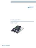
1 UG:015 Page 1 IntroductionThe 6123 Converter housed in a Package (ChiP) Bus Converter Module (BCM) evaluation board described in this document is designed to be used with the BCM family of isolated , DC-DC Bus converters. The Evaluation board is used for both the Analog -control and digital-control BCM focus of this document is to assist the user in evaluating the Analog -control version of the BCM BCM evaluation board can be configured for various enabling and fault-monitoring schemes, as well as to exercise various loading conditions depending on the application requirements.
2 The evaluation board can be used to evaluate BCMs in either a stand-alone configuration, or as an array of is important to remember the fast response of BCMs can readily show the limitations of the source, load and associated wiring connected to the evaluation board. Care should be exercised to minimize the stray source and load impedance in order to fully exercise the to the appropriate data sheet for performance and operating limits. Data sheets are available at Options:1. Apply input voltage greater than the BCM undervoltage lockout (Default)2.
3 On-board mechanical switch3. External control using available test pointFault Monitor Options:1. On-board LED: the VAUX pin drives a visible LED for visual feedback on the BCM status such as enabled or fault HV and LV 6123 ChiP BCM Bus Converter Evaluation Board User Guide USER GUIDE | UG:015 Peter Makrum Applications EngineerContents PageIntroduction 1 Enable Options: 1 Fault Monitor Options: 1 Contents 2 Features 3 Board Description 3 General Components 3 Test Points Description 5 Bill of Materials 10 Recommended Test Equipment 11 Basic Connections 12 Board Operation Details 12 Thermal Considerations 12 Paralleling 13 UG:015 Page 2 IMPORTANT NOTICE:Hazardous voltages are present on the HV BCM Evaluation Board under power.
4 PERSONAL CONTACT WITH LINE VOLTAGE MAY RESULT IN SEVERE INJURY, DISABILITY, OR DEATH. IMPROPER OR UNSAFE HANDLING OF THIS BOARD MAY RESULT IN SERIOUS INJURY OR the precautions below entirely BEFORE using the BCM evaluation board. Do not operate the evaluation board unless appropriate bench safety precautions are in place to guarantee list below is not comprehensive and is not a substitute for common sense and good operation, the power devices and surrounding structures can be operated safely at high power and use caution when connecting and disconnecting test probes and interface lines to avoid inadvertent short circuits and contact with hot use a jumper in place of the testing electronic products always use approved safety glasses.
5 Follow good laboratory practice and creating ground loops when making measurements of the isolated input or output should be taken to protect the user from accidental contact when under should be taken to avoid reversing polarities if connecting to the opposite (solder) side of the product evaluation boards described in this document are designed for general laboratory evaluation and are not suitable for installation in end user to the specific BCM module data sheet for electrical, thermal, and mechanical product boards provide a convenient way to evaluate / demonstrate the performance of the Vicor BCM products.
6 Kelvin connections are provided for accurate voltage measurements on power nodes. Sockets are provided to permit quick installation and changing of bulk-filtering capacitors. The evaluation board also provides lugs for Input / output connections, test points and sockets for easy connection to standard test equipment and a high performance air-cooled heat sink evaluation board arrives with the following contents:nn1 x BCM evaluation boardnn1 x Top heat sink pre-installed as well as a bottom of the ChiP heat sink when applicablenn1 x Hardware kit.
7 Nn1 x through hole aluminum-electrolytic output capacitor (C121)nn3 x Connector receptacle 8 positionnn2 x Connector socket 2 positionnn5 x Size 10 screws, lugs and washers UG:015 Page 3 FeaturesThe BCM evaluation board has the following features:1. Input and output lugs for source and load connections2. Appropriately rated input fuse3. Input aluminum electrolytic capacitor for additional source decoupling4. Basic output filtering footprint, including sockets to add through hole output aluminum electrolytic capacitors5.
8 Toggle switch for enabling and disabling the BCM via the enable (EN) pin6. Oscilloscope probe jack for accurate, high-frequency output voltage measurements7. Connectors for BCM signal pins (TM, EN, and VAUX) and temperature monitor filtered signal8. Kelvin voltage test points for all power pins9. Top and bottom heat sink assembly for the BCM where applicableBoard DescriptionThe following section provides a detailed description of the evaluation board components, test points and Components1. BCM (P S01)2.
9 Input lugs: Sized for #10 hardware. Use for making connection to the input source. This board does not contain reverse polarity protection. Check for proper polarity before applying the power. It is important to remember that noise from the source and voltage drops will appear at the output of the bus converter multiplied by transformation ratio (K). The K factor is the ratio of the output voltage to the input voltage (VOUT / VIN).3. Input fuse (F101 & F102): Appropriately rated for the BCM model installed on the board.
10 The fuse is not meant to protect the Input filtering: aluminum electrolytic input capacitor (C101).5. Enable / Disable switch (SW101): When actuator is in top position towards ON text on the board, the (EN) pin will be open and the BCM will be enabled. When actuator is in bottom position towards OFF text on the board, the (EN) pin will be connected to ( IN) pin and the BCM will be disabled. When switch (SW101) is ON , an external voltage source can control the EN pin Signal connector (J102): provides access to the bus converter signal pins (TM, EN, and VAUX) as well as (TM_DC) externally filtered signal.
