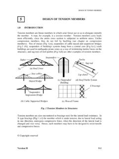
Transcription of UK N.A. Value Tension Members M0
1 Steel Design to Eurocode 3 Tension Members As the tensile force increases on a member it will straighten out as the load is increased. For a member that is purely in Tension , we do not need to worry about the section classification since it will not buckle locally. A Tension member fails when it reached the ultimate stress and the failure load is independent of the length of the member. Tension Members are generally designed using rolled section, bars or flats. Tensile Resistance EN 1993-1-1 Clause (1) Equation states that the design tensile force (Nt,Ed) must be less than the design tensile resistance moment (Nt,Rd) The tensile resistance is limited by the lesser of: Design Plastic Resistance Npl,Rd Design Ultimate Resistance Nu,Rd Design Plastic Resistance, Npl,Rd Npl,Rd is the plastic design resistance, and is concerned with the yielding of the gross cross-section.
2 Equation gives the expression used to calculate Npl,Rd: Design Ultimate Resistance, Nu,Rd Nu,Rd is the design ultimate resistance of the net cross-section, and is concerns with the ultimate fracture of the net cross-section, which will normally occur at fastener holes. Equation gives the expression used to calculate Nu,Rd: Partial Factors M M UK Value M0 Resistance of cross-sections M2 Resistance of cross-sections in Tension to fracture Characteristic Strengths fy and fu The UK National Annex says you should get the values of fy and fu from the product standards. For hot-rolled sections you can use the table below. Steel grade fy (N/mm2) fu (N/mm2) t 16 16 < t 40 40 < t 63 63 < t 80 t < 3 3 < t 100 S 275 275 265 255 245 430-580 410-560 S 355 355 345 335 325 510-680 470-630 Extract from Table 7 of EN 10025-2 Anet for Non staggered fasteners Anet = A d0t Anet for Staggered Fasteners: The total area to be deducted should be taken as the greater of: a) The maximum sum of the sectional areas of the holes on any line perpendicular to the member axis b) ( ) ( ) ( ) where.
3 T is the thickness of the plate p is the spacing of the centres of the same two holes measured perpendicular to the member axis s is the staggered pitch of the two consecutive holes n is the number of holes extending in any diagonal or zig-zag line progressively across the section d0 is the diameter of the hole Angles with welded end connections Clause (2) of EN 1993-1-8 states that for an equal angle, or unequal angle welded along its larger leg, the effective area = gross area. Angles Connected by a single row of bolts Refer to EN 1993-1-8. For 1 bolt: For 2 bolts: For 3 or more bolts: Values of reduction factors 2 and 3 can be found in Table : Pitch p1 d0 d0 2 (for 2 bolts) 3 (for 3 or more bolts) Note: For intermediate values of pitch p1 values of may be determined by linear interpolation.
4 EN 1993-1-8 Table Tension Member Design Steps Summary 1. Determine the design axial load NEd 2. Choose a section 3. Find fy and fu from the product standards 4. Get the gross area A and the net area Anet 5. Substitute the values into the equations to work out Npl,Rd and Nu,Rd For angles connected by a single row of bolts, use the required equation to work out Nu,Rd from EN 1993-1-8 which will depend on the number of bolts. For 1 bolt: For 2 bolts: For 3 or more bolts: 6. The design tensile Resistance is the lesser of the values of Npl,Rd and Nu,Rd 7. Carry out the Tension check: ( ) ( ) ( ) ( ) ( ) ( ) ( ) ( ) ( )