Transcription of UltraCMOS® Power Limiter Modes and Applications
1 UltraCMOS Power Limiter Modes and ApplicationsApplication Note 54 2017, Peregrine Semiconductor Corporation. All rights reserved. Headquarters: 9380 Carroll Park Drive, San Diego, CA, 92121 Application NoteDOC-77789-1 (01/2017) Semiconductor s UltraCMOS Power limiters provide a monolithic alternative to discrete, PIN-diode limiters. They reduce design complexity by offering a drop-in solution with no external bias components. Peregrine s Power limiters have two operating Modes Power limiting and Power reflecting. They feature adjustable P1dB threshold, high linearity perfor-mance, fast response and recovery time and superior ESD protection.
2 Application examples include test and measurement (T&M) equipment, communication radio frequency front-end (RFFE) modules and weather radar RF Power , intentional jamming and ESD events can wreak havoc on an electronic device. As a result, RF designers for Applications such as T&M equipment, RFFE modules, land mobile radios (LMRs) and radar systems must take steps to ensure the Power reliability of their devices. These types of Applications require repeatable and reliable Power protection. To protect circuitry, Power -limiting devices are used to reduce the extra signal strength that might damage the rest of a design's components.
3 Below a threshold (P1dB) level, the Limiter passes the input signal to the output without attenuation. At the threshold, the Limiter limits the amount of input Power that is passed to the output, up to the maximum , the industry has relied on PIN-diode Power Limiter circuits and multiple external components to deliver Power protection. With a PIN diode, the input signal is shunted to ground. PIN diodes are known for their high maximum Power handling and low insertion loss. But PIN diodes are also plagued with slow response and recovery time, poor linearity, low ESD ratings and require DC blocking capacitors.
4 Additionally, PIN diodes take a significant amount of time to design and validate and cannot be easily integrated into a system. Peregrine s UltraCMOS Power limiters provide an all-in-one solution and are a simple and reliable alternative to discrete, PIN-diode limiters. Compared to PIN diodes, UltraCMOS Power limiters provide a 10 100x improvement in response and recovery time, deliver a greater than 10 30 dB linearity (IIP3) improvement and offer a 20x improvement in ESD protection. In addition, UltraCMOS Power limiters are 8x smaller than the board space required by PIN-diode solutions.
5 Finally, the limiting threshold can be adjusted through a high impedance voltage control pin (VCTRL), eliminating the need for external components such as DC blocking capacitors, RF choke inductors and bias resistors. Application Note 54 UltraCMOS Power LimitersPage 2 DOC-77789-1 (01/2017) ModesUltraCMOS Power limiters have symmetric RF ports that limit incident Power in both biased and unbiased conditions (Figure 1). The devices feature two operating Modes Power limiting and Power reflecting to maximize performance and flexibility. The operating mode can be selected through the VCTRL pin.
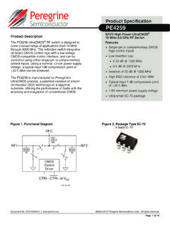
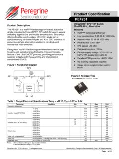
6 For effective Power Limiter operation, certain parameters and capabilities must be considered. These considerations include insertion loss, Power threshold, ESD protection, Power transfer curves and transient Limiting ModeIn Power limiting mode, the UltraCMOS Power Limiter is operated within two regions as shown in Figure 2 the linear region and the limiting region. The threshold is adjusted through the VCTRL pin that provides flexibility in the limiting behavior compared to PIN-diode limiters. Peregrine s Power limiters act as a diode Limiter without an external sensor or loop control 1 Product SymbolVoltage Control and ESDRF1 VCTRLRF2 POUTP1dBPINF igure 2 Power Limiting Mode OperationThresholdThresholdPOUTPINS21(IL )Linear RegionLimiting RegionPINA pplication Note 54 UltraCMOS Power LimitersDOC-77789-1 (01/2017)Page RegionIn the linear region (Figure 2), the UltraCMOS Power Limiter is invisible to the load, and it features very low insertion loss and high linearity.
7 Insertion loss defines the small signal throughput loss (S21) of the Limiter . The Peregrine Power Limiter demonstrates excellent linearity with HaRP technology, and delivers 10 30 dB higher IIP3 than PIN diodes at the same P1dB level. These monolithic Power limiters also have fast response and recovery times that are typically one nanosecond (1 ns).Limiting RegionRegarding limiting region operation (Figure 2), when the incoming RF signal Power exceeds the limiting threshold set through the VCTRL pin, the device limits the input Power . Large signal amplitude results in higher gate voltage and the saturation or breakdown of transistors.
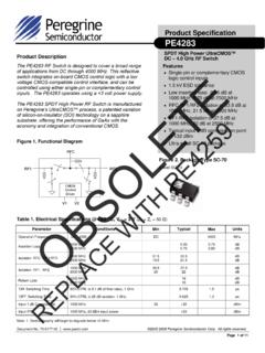
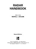
8 The limiting effect occurs at both the positive and negative peak of the signal and is symmetrical on both peaks (Figure 3).Figure 3 Limiting Region Operation+VoltageTime00 Signal without LimitingSignal with Limiting VoltageApplication Note 54 UltraCMOS Power LimitersPage 4 DOC-77789-1 (01/2017) Reflecting ModeIn Power reflecting mode, the UltraCMOS Power Limiter is used for Power protection in extreme conditions, and the device reflects most of the incident Power back to the source. In this mode, the Power Limiter is acting as a shunt using a shunt SPST switch for protection, the SPST switch is off (Figure 4) during normal receive operation.
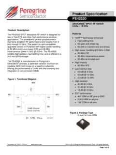
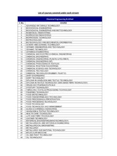
9 The system monitors the input Power level and compares it with a preset reference level. When input Power reaches that level, the system instructs the SPST switch to turn on, shorting the input to ground. When the SPST switch is on and shorting the signal to ground, the system loses its ability to monitor input Power . It must periodically turn off the SPST switch to check the input level condition. LFigure 4 Using a Shunt SPST Switch for ProtectionInput PowerThresholdOutput Power to ReceiverSeparated by SPST ON Mode AttenuationInputPortReference LevelSignalDetectorArbitratorReceiverSPS TA pplication Note 54 UltraCMOS Power LimitersDOC-77789-1 (01/2017)Page an UltraCMOS Power Limiter is used as a shunt SPST switch (Figure 5), VCTRL is set to to turn the switch ON and VCTRL is set to to to turn the switch OFF.
10 IIP3 is greater than 60 dBm in the OFF state and the ON mode attenuation is approximately 40 dB. Switching time is 1 5 SPST Switch Mode 12 10 8 6 4 20242022242628303234363840 Pout(dBm)Pin (dBm)Pout (dBm)Application Note 54 UltraCMOS Power LimitersPage 6 DOC-77789-1 (01/2017) limiters offer repeatable and reliable Power protection to Applications such as T&M equipment, communication RFFE modules and weather radar 1: Test and MeasurementMeasurement equipment needs a Power Limiter to protect RF ports from unexpected Power surges (Figure 6). Peregrine s Power limiters feature a high threshold (P1dB greater than 25 dBm) and high linearity in the linear region.