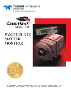
Transcription of ULTRAFLOW 150 - Welcome To Teledyne Monitor …
1 ULTRASONIC GAS FLOW AND TEMPERATURE MONITORULTRAFLOW 150 ULTRAFLOW 150 s state-of-the-art signal processing and innovative modularity offers customers incomparable performance , accuracy, flexibility and a maintenance-free solution amongst all flow , non-contacting tech-nique greatly reduces maintenanceThe ULTRAFLOW 150 is a patented ad-vance in continuous flow measurement systems for small and large stacks and ducts. Transducers are non-intrusively mounted in Teflon housing and are protected from flue gas and particulate with continuous purge air. This non-contacting method mitigates mainte-nance and ensures long term operation unlike intrusive pitot, thermal systems, optical scintillation and reflective ultrasonic measurement independent of temperature, pressure and density of flue gasThe system measures the transit times t1 and t2 of the tone bursts between the pair of transducers with a 50 nano-second transit time resolution.
2 The equation for determining velocity is:Fv = [L/(2cos )][(t2-t1)/t2t1]Where L is the pathlength and is the angle between the line-of-sight of the transducers and the nominal flow direction. The flue gas composition has no influence on the calculation of velocity and therefore knowing only the geometry and transit times are suf-ficient to calculate the average response is exceptionally term drift 1%Resolution is better than Long term drift is 1% over the life of the instrument. A barometric pressure transducer option is available to cor-rect back to ULTRAFLOW 150 integrates the infinitesimal velocity vectors along the transducer path to calculate veloc-ity as well as temperature. A normal sampling cycle consists of many measurements in each direction over a time period that can be as short as 5 seconds. Dynamic calibration checks verify all system componentsUltraflow 150 meets all 40 CFR75 requirements, NOX budget rules and new RATA standards.
3 Calibration checks are conducted once per day or on command to fully test the signal transmission, reception, processing display and output; , a full system integrity test not available via compet-ing technologies. The flow character-ization curve is also tested under this protocol. No adjustments are ever made to the zero and span since the Monitor is drift free. Calibrations can be initiated manually, automatically, by a digital input or via the front panel signal processing provides greater accuracy, quicker response time and excellent resolutionUltraflow 150 utilizes a Field Pro-grammable Gate Array (FPGA) to determine the time of flight based on a proprietary peak finding algorithm. Our peak finding algorithm enables response times of down to 5 seconds; making the 150 ideal for hazardous waste combustors and process to use Enhanced Remote PanelThe remote display features easy-to-use menu structures that make con-figuration of the flow Monitor simple and easy without the need of a laptop.
4 I/O includes four analog outputs, eight digital inputs, eight contact outputs, RS232, 422, 485 or LONWORKS network communication. A large LCD display makes viewing easy through-out a control duty components are easy to installThe ULTRAFLOW 150 has simplified placement requirements, using cus-tomer-installed, 3 , schedule 40 pipe as mounting ports. (For other pipe sizes, consult factory). Teledyne Monitor Labs provides all system components. Materials of con-struction for the Transducer Interface Enclosure and j-boxes are stainless steel. Transducer assemblies are aluminum protected by acid resistent epoxy paint. X Pattern configuration eliminates a second platformThe ULTRAFLOW 150 has the capabil-ity of measuring flow through either a single or dual set of transducers. A dual set of transducers is typically re-ferred to as our X Pattern. An X Pattern eliminates any adverse affects due to applications that exhibit a pitch flow; enables nearly 100% availability and may institute equations for determining tem-perature are :Cs = (L/2)[(t2+t1)/t2t1]T = r Cs2 Where Cs is the speed of sound and r is a correction factor that relates the speed of sound to a specific gas composition.
5 Temperative MeasurementsIn many cases, due to the 150 s improved resolution, low angles of installation (typ. 5ft. vertical offsets from a single platform) are possible. In some demanding applications, an X - pattern may be Interface Enclosure (TIE)Electrical signals corre-sponding to acoustic transmit and receive signals are con-veyed via cables between the transducers and the TIE. The TIE houses preamp /driver boards that amplify receive sig-nals and transmit pulses. A sig-nal processing board containing an FPGA controls timing, data collection, filtering, boxcar integration and other func-tions. A microprocessor board evaluates the box car data and determines time of flight, flow velocity, volume, speed of sound, temperature and signal to noise ratio. All these data values may be viewed via the Enhanced Remote Panel or the optional Local User Interface (LUI).
6 Purge Air SystemTransducer AssembliesEach of the two transducers alternately acts as transmitter and receiver. The purge noz-zles are constructed of acid-resistant Teflon with stainless steel or Hastelloy hardware for easy cleaning and a long service life. Each transducer assembly is made of lightweight aluminum stock and can be easily extracted from its mounting port by disengaging four draw latches. Enhanced Remote PanelUses a large, back-lit, LCD graphics display with English-language menu-driven screens, providing ready access to all information needed for full use of the system. In addition, the user can graph up to the most recent 100 values of a selected parameter, such as: Volumetric Flow and Temperature Calibration ValuesThe keypad, a rugged 20-button ensemble inlaid under a tough, hard coated, scratch and chemical-resistant coating, can be used to: Display Volumetric Flow, Velocity and Temperature Identify the Cause of Alarm or Malfunction Configure the Analog Outputs Edit Parameters such as Path Length Set Alarm Values for High or Low Volumetric Flow or Temperature and Out of Load Linearization Curves for Correlation to Method 2 Standard with the Enhanced Remote Panel is a security keylock for protection of im-portant calibration parameters.
7 System elements communicate over a single twisted pair (FTT) using LONWORKS communication protocol. Bright LED indicator lights are used to indicate faults and alarms. The four optically-isolated analog outputs, normally pack-aged within the Enhanced Remote Panel, can also be offered in a separate housing for convenient transducer assemblies are normally kept dry and clean by purge air. Depending on the application, the optimal installation may consist of dual blowers (a separate purge blower for each side of the stack), a single blower con-figuration with flow splitter to reliably send equal amounts of purge air to each side of the stack, or no blowers at all where a reliable negative-draft process is present. A no blower system has an in-line filter to clean up the ambient air. When blowers are used, the normal purge system consists of blow-ers, hoses, air filters, mounting plates and a protective weather cover.
8 Teledyne Monitor Labs Engineering will recommend the optimum configuration for each measurements View New Signal-to-Noise Diagnostics View Flow Data Pre and Post LinerizationEthernet InterfaceThe ULTRAFLOW 150 Enhanced Remote Panel now features a 10/100 BaseT Ethernet in-terface as standard equipment. This capability provides a multilevel password protected user interface to TCP/IP networks such as LAN's or the Internet. Client side user inter-face access is via standard web browsers. Simultaneous Modbus TCP access to instru-ment parameters and emission data is also Operation and Mainte-nance Manual is provided with the ULTRAFLOW 150. In addition, periodic hands-on training classes are conducted at the Teledyne Monitor Labs facility. Training classes may also be scheduled at the customer s site. WarrantyThe ULTRAFLOW 150 is covered by Teledyne Monitor Labs Commercial performance Warranty provided certain condi-tions are met.
9 Consult the factory for and Support ServicesConsult the factory for details on Teledyne Monitor Labs complete line of Service and Maintenance Programs, in addition to a user support line available on a 24-hour :Long-Term Repeatability:Relative Accuracy:Response Time:Flow Measurement:0-200ft/sec (0-61m/sec) ( )+ (+ )Site dependent, see Commercial PerformanceWarranty. Typically <5% above 10/ft/secAs low as 5 sec (adjustable)Initial Calibration:Factory calibration based on duct geometry plus flow data. Available for site specific calibration against pitot tube :+/- 1% reading over full range of rated ambient temperature and line Conditions:Temperature:-40 to 650F (-40 to +343 C) depending on stack size and flow speed. Consult :-30 to 20 inches of H2 OMoisture:Dry to saturated, including condensed waterParticulate:</=3000 mg/m Duct Size:Diameter:From 3 - 45 Ft.
10 ( - 14M) :Accuracy:+/- 3 F ( C) for most reasonably stable combustion applicationsDisplay Resolution:</= (C or F)Power:TIE:85-245 VAC, 47-63Hz, Single Phase, 40 VA Maximum FusesPower Supply Board: Amp Time Delay, 250V, TR5 Mounting:Process Connection:Mounting plates furnished for welding to 3 " Sch. 40 pipe (supplied by customer) with squeeze rings, seals and stainless steel hardware provided. For other pipe sizes, consult :Output:RS-232C or LONWORKS network protocolEnhanced Remote Panel:Display Type:Graphics mode liquid crystal with LED backlightDisplay Resolution:240 x 128 Indicating LED s:Fault, Alarm, PowerUser Input Controls:20-key keypad, security keyswitchDiagnostics:Numerical and English descriptive diagnostic codesSecurity:Both security code and key switchAlarms & Faults:Cal out of tolerance, malfunction, purge failMulti I/O Board Characteristics:Analog Outputs:Four outputs, 4-20mA current type:Isolation: optical and capacitive barriers: channel tochannel, channel to circuit common and earthDigital Inputs:Eight Inputs, Modes: Isolated (5 VDC-24 VDC user supplied) and Non-isolated (dry contact)Relay Outputs:Eight Outputs, or (Single Pole Single Throw, Normally Open or Normally Closed [jumper selectable])(VS.)