Transcription of Ultralow Distortion, Wide Bandwidth Voltage …
1 Ultralow distortion , wide BandwidthVoltage feedback Op AmpsData Sheet AD9631/AD9632 Rev. D Document feedback Information furnished by analog devices is believed to be accurate and reliable. However, no responsibility is assumed by analog devices for its use, nor for any infringements of patents or other rights of third parties that may result from its use. Specifications subject to change without notice. No license is granted by implication or otherwise under any patent or patent rights of analog devices . Trademarks and registered trademarks are the property of their respective owners. One Technology Way, Box 9106, Norwood, MA 02062-9106, : 2014 analog devices , Inc. All rights reserved. Technical Support FEATURES wide Bandwidth AD9631, G = +1 AD9632, G = +2 Small signal AD9631, 320 MHz AD9632, 250 MHz Large signal (4 V p-p) AD9631, 175 MHz AD9632, 180 MHz Ultralow distortion (SFDR), low noise 113 dBc typical @ 1 MHz 95 dBc typical @ 5 MHz 72 dBc typical @ 20 MHz 46 dBm third-order intercept @ 25 MHz nV/ Hz spectral noise density High speed Slew rate: 1300 V/ s Settling time to , 2 V step: 16 ns 3 V to 5 V supply operation 17 mA supply current APPLICATIONS ADC input driver Differential amplifiers IF/RF amplifiers Pulse amplifiers Professional video DAC current to Voltage Baseband and video communications Pin diode receivers Active filters/integrators/log amps GENERAL DESCRIPTION The AD9631/AD9632 are very high speed and wide Bandwidth amplifiers.
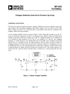
2 The AD9631 is unity gain stable. The AD9632 is stable at gains of 2 or greater. Using a Voltage feedback architecture, the exceptional settling time, Bandwidth , and low distortion of the AD9631/AD9632 meet the requirements of many applications that previously depended on current feed-back amplifiers. Its classical op amp structure works much more predictably in many designs. PIN CONFIGURATION Figure 1. 8-Lead PDIP (N) and SOIC (R) Packages A proprietary design architecture has produced an amplifier that combines many of the best characteristics of both current feedback and Voltage feedback amplifiers. The AD9631/AD9632 exhibit exceptionally fast and accurate pulse response (16 ns to ) as well as extremely wide small signal and large signal Bandwidth and Ultralow distortion . The AD9631 achieves 72 dBc at 20 MHz, 320 MHz small signal Bandwidth , and 175 MHz large signal bandwidths.
3 These characteristics position the AD9631/AD9632 ideally for driving flash as well as high resolution ADCs. Additionally, the balanced high impedance inputs of the Voltage feedback archi-tecture allow maximum flexibility when designing active filters. The AD9631/AD9632 are offered in the industrial ( 40 C to +85 C) temperature range. They are available in PDIP and SOIC. Figure 2. AD9631 Harmonic distortion vs. Frequency, G = +1 1234NC INPUT+INPUT VS8765 NCAD9631/AD9632 TOP VIEW(Not to Scale)+VSOUTPUTNCNOTES1. NC = NO 30 40 50 60 70 80 90 100 110 120 13010k100k1M10M100 MHARMONIC distortion (dBc)FREQUENCY (Hz)THIRD HARMONICSECOND HARMONICVS = 5 VRL = 500 VOUT = 2V p-p00601-002AD9631/AD9632 Data Sheet Rev. D | Page 2 of 20 TABLE OF CONTENTS Features .. 1 Applications .. 1 General Description .. 1 Pin Configuration .. 1 Revision History.
4 2 Specifications .. 3 Electrical Characteristics .. 3 Absolute Maximum Ratings .. 5 Metallization Photo .. 5 Thermal Resistance .. 5 Maximum Power Dissipation .. 5 ESD Caution .. 5 Typical Performance Characteristics .. 6 Theory of Operation .. 15 15 feedback Resistor 15 Pulse Response .. 16 Large Signal Performance .. 16 Power Supply Bypassing .. 16 Driving Capacitive Loads .. 16 Applications Information .. 17 Operation as a Video Line Driver .. 17 Active Filters .. 17 analog -to-Digital Converter (ADC) Driver .. 18 Layout Considerations .. 18 Outline Dimensions .. 19 Ordering Guide .. 20 REVISION HISTORY 2/14 Rev. C to Rev. D Changes to Figure 33 .. 10 Changes to analog -to-Digital Converter (ADC) Driver Section and Figure 66 .. 18 Updated Outline Dimensions .. 19 Changes to Ordering Guide .. 20 7/03 Rev. B to Rev. C Deleted Evaluation Boards information.
5 Universal Deleted military CERDIP version .. Universal Change to Absolute Maximum Ratings .. 3 Change to TPC 4 .. 4 Change to TPC 5 Change to Figure 6 .. 14 Updated Outline Dimensions .. 17 1/03 Rev. A to Rev. B Deleted DIP (N) Inverter, SOIC (R) Inverter, and DIP (N) Noninverter Evaluation Boards in Figures 12 14 .. 17 Updated Outline Dimensions .. 18 Data Sheet AD9631/AD9632 Rev. D | Page 3 of 20 SPECIFICATIONS ELECTRICAL CHARACTERISTICS VS = 5 V; RLOAD = 100 ; AV = 1 (AD9631); AV = 2 (AD9632), unless otherwise noted. Table 1. Parameter Test Conditions/Comments AD9631 AD9632 Unit Min Typ Max Min Typ Max DYNAMIC PERFORMANCE Bandwidth ( 3 dB) Small Signal VOUT V p-p 220 320 180 250 MHz Large Signal1 VOUT = 4 V p-p 150 175 155 180 MHz Bandwidth for dB Flatness VOUT = 300 mV p-p RF = 140 (AD9631); RF = 425 (AD9632) 130 130 MHz Slew Rate, Average VOUT = 4 V step 1000 1300 1200 1500 V/ s Rise/Fall Time VOUT = V step ns VOUT = 4 V step ns Settling Time To VOUT = 2 V step 11 11 ns To VOUT = 2 V step 16 16 ns HARMONIC/NOISE PERFORMANCE Second Harmonic distortion 2 V p-p; 20 MHz, RL = 100 64 57 54 47 dBc RL = 500 72 65 72 65 dBc Third Harmonic distortion 2 V p-p.
6 20 MHz, RL = 100 76 69 74 67 dBc RL = 500 81 74 81 74 dBc Third-Order Intercept 25 MHz 46 41 dBm Noise Figure RS = 50 18 14 dB Input Voltage Noise 1 MHz to 200 MHz nA/ Hz Input Current Noise 1 MHz to 200 MHz pA/ Hz Average Equivalent Integrated Input Noise Voltage MHz to 200 MHz 100 60 V rms Differential Gain Error ( MHz) RL = 150 % Differential Phase Error ( MHz) RL = 150 Degree Phase Nonlinearity DC to 100 MHz Degree DC PERFORMANCE2 RL = 150 Input Offset Voltage3 3 10 2 5 mV TMIN TMAX 13 8 mV Offset Voltage Drift 10 10 V/ C Input Bias Current 2 7 2 7 A TMIN TMAX 10 10 A Input Offset Current 3 3 A TMIN TMAX 5 5 A Common-Mode Rejection Ratio VCM = V 70 90 70 90 dB Open-Loop Gain VOUT = V 46 52 46 52 dB TMIN TMAX 40 40 dB INPUT CHARACTERISTICS Input Resistance 500 500 k Input Capacitance pF Input Common-Mode Voltage Range V AD9631/AD9632 Data Sheet Rev.
7 D | Page 4 of 20 Parameter Test Conditions/Comments AD9631 AD9632 Unit Min Typ Max Min Typ Max OUTPUT CHARACTERISTICS Output Voltage Range RL = 150 V Output Current 70 70 mA Output Resistance Short Circuit Current 240 240 mA POWER SUPPLY Operating Range V Quiescent Current 17 18 16 17 mA TMIN TMAX 21 20 mA Power Supply Rejection Ratio TMIN TMAX 50 60 56 66 dB 1 See the Absolute Maximum Ratings and Theory of Operation sections of this data sheet. 2 Measured at AV = 50. 3 Measured with respect to the inverting input. Data Sheet AD9631/AD9632 Rev. D | Page 5 of 20 ABSOLUTE MAXIMUM RATINGS Table 2. Parameter Rating Supply Voltage (+VS to VS) V Voltage Swing Bandwidth Product 550 V MHz Internal Power Dissipation PDIP (N) W SOIC (R) W Input Voltage (Common Mode) VS Differential Input Voltage V Output Short Circuit Duration Observe Power Derating Curves Storage Temperature Range 65 C to +125 C Operating Temperature Range (A Grade) 40 C to +85 C Lead Temperature Range (Soldering 10 sec) 300 C Stresses above those listed under Absolute Maximum Ratings may cause permanent damage to the device.
8 This is a stress rating only; functional operation of the device at these or any other conditions above those indicated in the operational section of this specification is not implied. Exposure to absolute maximum rating conditions for extended periods may affect device reliability. METALLIZATION PHOTO Figure 3. Dimensions shown in inches and (millimeters) Connect Substrate to VS THERMAL RESISTANCE Table 3. Package Type1 JA Unit 8-Lead PDIP (N) 90 C/W 8-Lead SOIC (R) 140 C/W 1 For device in free air. MAXIMUM POWER DISSIPATION The maximum power that can be safely dissipated by these devices is limited by the associated rise in junction temperature. The maximum safe junction temperature for plastic encapsu-lated devices is determined by the glass transition temperature of the plastic, approximately 150 C.
9 Exceeding this limit tempo-rarily may cause a shift in parametric performance due to a change in the stresses exerted on the die by the package. Exceeding a junction temperature of 175 C for an extended period can result in device failure. While the AD9631 and AD9632 are internally short circuit protected, this may not be sufficient to guarantee that the max-imum junction temperature (150 C) is not exceeded under all conditions. To ensure proper operation, it is necessary to observe the maximum power derating curves. Figure 4. Maximum Power Dissipation vs. Temperature ESD CAUTION AD9631AD9632 IN IN2+VS76 OUT2+VS76 OUT3+IN4 VS3+IN4 ( ) ( ) ( ) 50 40 30 20 10 010 20 30 40 50 60 70 80 90 MAXIMUM POWER DISSIPATION (W)AMBIENT TEMPERATURE ( C)8-LEAD SOIC PACKAGE8-LEAD PDIP PACKAGETJ = 150 C00601-004AD9631/AD9632 Data Sheet Rev.
10 D | Page 6 of 20 TYPICAL PERFORMANCE CHARACTERISTICS Figure 5. AD9631 Noninverting Configuration, G = +1 Figure 6. AD9631 Large Signal Transient Response; VOUT = 4 V p-p, G = +1, RF = 250 Figure 7. AD9631 Small Signal Transient Response; VOUT = 400 mV p-p, G = +1, RF = 140 Figure 8. AD9631 Inverting Configuration, G = 1 Figure 9. AD9631 Large Signal Transient Response; VOUT = 4 V p-p, G = 1, RF = RIN = 267 Figure 10. AD9631 Small Signal Transient Response; VOUT = 400 mV p-p, G = 1, RF = RIN = 267 AD9631+ F10 F10 F VSRF130 VINRL = 100 VOUTPULSEGENERATORTR/TF = F10 F10 F+VS VSRFRL = 100 VOUTPULSEGENERATORTR/TF = 267 VIN100 00601-0081V5ns00601-009100mV5ns00601-010 Data Sheet AD9631/AD9632 Rev. D | Page 7 of 20 Figure 11. AD9632 Noninverting Configuration, G = +2 Figure 12. AD9632 Large Signal Transient Response; VOUT = 4 V p-p, G = +2, RF = RIN = 422 Figure 13.