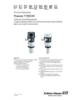
Transcription of Ultrasonic Level Measurement e
1 KA 042F/00/a3 TFMU 130, 131, 230, 231, 232eUltrasonic Level MeasurementHauser+EndressThe Power of Know HoweQuick reference guide: calibrationmore informationpage 17more informationpage 20 upwards0%4mA20 mA100%quick and easy without displaymore functions with plugged-in display3. Empty calibration V0H1 Input:4. Full calibration V0H2 Input:5. Applications V0H3 Input:E(m/ft)F(m/ft)4:Conveyor belt3:Bulk solids2:Dome cover1:Rapid levelchangeResetFull calibrationFEmpty calibrationE1. Reset instrument V9H5 Input:2. Select length unit V8H2 Input:mft3330:1:0.
2 LiquidV+H +HauserSummaryNotes on Safety4 Safety Conventions and Symbols5 Function6 Application and Measuring Ranges6 Measuring System7 Installation8 Blocking Distance8 Housing8 Protective Hood for Electronic Housing8 Mounting FMU 130, 131, 230, 231with Counter Nut9with Welded Sleeve9on a Nozzle9with Mounting Bracket10with Adapter Flange10 Mounting FMU 232with Mounting Bracket11with Slip-On Flange11 Electrical Connection12 Cabling12 Connection Diagramsupwards 12 Functional Display15 Summary of Operating Procedures16 Key Operation without Display.
3 Without Matrix 16 Reset17 Calibration17 Operating via the Matrix18 Local Pushbutton Operation with Plug-In Display18 Operation via Commulog VU 260 Z19 Operation via Universal HART Communicator DXR 27519 Configuration20 Calling Up Measured Values andMeasuring Point Information20 Calibration21 Linearization22 Set Current Output24 Other Possible Entries25 Simulation27 Locking27 Information on the Measuring Point28 Diagnosis and Trouble-Shooting28 Error Analysis29 INTENSOR Matrix31 HART Matrix32 Technical Data33 Software Development34 Index35eEndress+Hauser3 Notes on SafetyThe compact transmitters prosonic T FMU have been designed to operate safely inaccordance with current technical and safety standards and must be installed by qualifiedpersonnel according to the instructions in this manual.
4 The manufacturer accepts noresponsibility for any damage arising from incorrect use, installation or operation of theequipment. Changes or modifications to the equipment not expressly approved in theoperating instructions or by the bodies responsible for compliance may make the user'sauthority to use the equipment null and void. Damaged instruments which may be a safetyhazard must not be operated and are to be marked as in Hazardous AreasWhen used in explosion hazardous areas, the equipment must be installed in accordance withlocal regulations as well as with the technical and safety requirements on the measuring pointas specified in the accompanying 130/FMU 1312-wireExFMU 230/FMU 2312-wire and 4-wirenon ExFMU 2324-wireDust-ExAStandardxxBEEx ia IIC, Zone 1 / Atex II 2 GxJFM, Class I, Division 1 Groups A-D1)
5 XMFM, Class II, Division 1 Groups E-GxQCSA, Class I, Division 1, Groups A-D1)xRCSA, Class II, Division 1, Groups E-GxNCSA General PurposexxFBVS/DMT (St-Ex) Zone 10 / ATEX II1/3 DxInstallation and CommissioningInstallation, electrical connection, commissioning, operation and maintenance may only becarried out by trained and authorized personnel. The personnel must read and understandthese operating instructions before carrying them instruments may only be operated by trained personnel authorized by the plant instructions given in this manual are to be followed )
6 For versionFMU X3XA onlyFMU X3X 4 Endress+HauserSafety Conventions andSymbolsIn order to highlight safety-relevant oralternative operating procedures in themanual, the following conventions have beenused, each indicated by a correspondingicon in the ProtectionElectrical SymbolsSymbolMeaningDevice certified for use in explosion hazardous areasIf the Porsonic T has this symbol embossed on its name plate it can be installed in anexplosion hazardous hazardous areaSymbol used in drawings to indicate explosion hazardous areas. Devices located in and wiring entering areas with the designation explosion hazardous areas must conform with the stated type of area (non-explosion hazardous area)Symbol used in drawings to indicate, if necessary, non-explosion hazardous areas.
7 Devices located in safe areas still require a certificate if their outputs run into explosionhazardous voltageA terminal to which or from which a direct current or voltage may be applied or voltageA terminal to which or from which an alternating (sine-wave) current or voltage may beapplied or terminalA grounded terminal, which as far as the operator is concerned, is already grounded bymeans of an earth grounding grounding (earth) terminalA terminal which must be connected to earth ground prior to making any otherconnection to the connection (earth bonding)A connection made to the plant grounding system which may be of type neutral staror equipotential line according to national or company +Hauser5 FunctionApplication and MeasuringRanges2-Wire, mA Loop-Powered 4-Wire, Including Mains Power SupplyAn Ultrasonic emitter (sensor) mounted above the product is electrically excited and directs anultrasonic pulse through the air towards the product.
8 This pulse is reflected back from thesurface of the product. The echoes partially reflected are detected by the same sensor, nowacting as a receiver, and converted back into an electrical signal. The time taken betweentransmission and reception of the pulse thetime-of-flight is directly proportional to thedistance between the sensor and the product prosonic T is a compact Ultrasonic transmitter for continuous non-contact levelmeasurement in liquids and in coarse-grained or pelleted solids (grain size from 4 in).It has an integrated temperature sensor for time-of-flight compensation.
9 The prosonic T seriesconsists of three transmitters, which can be equipped with one of several electronic modules,with graduated measuring ranges from m ( ft) ProcessconnectionMeasuring rangesliquid:solid:FMU 13011/2" 1312" 23011/2" 2312" 2324" versionswithoutcommunicationFFAA HARTBBCC INTENSORAABB PROFIBUS-PAPPPPPS ensor/ ProcessconnectionMeasuring rangesliquid:solid:FMU 23011/2" 2312" 2324" versionspower (2-wire)PPPPPPPPPFMU X3 XFMU X3X6 Endress+HauserMeasuring System2-Wire, "Loop-Powered" Power supply: via the transmitter powerpack PLC, with FMU 130, 131connection via the Ex isolator (Zenerbarrier),operation: via handheld terminal,protocols INTENSOR or HART FXN 671: operation via Rackbus orhandheld terminal,protocol INTENSOR Silometer FMX 770: operation viaCommutec transmitter,protocol INTENSOR FMU 130, FMU 131 only: connection toPROFIBUS-PA bus for up to 10transmitters, operated by a PC Commubox.
10 Interface to a PC for Smart transmitters,operated by a PC or protocol HART4-Wire, Separate Power Supply Operation via HART protocol:point-to-point using handheld terminal orPC (Commubox)FMX 77012543 FXN 671mA1+PLCEx isolatorRackbusRackbusFMX mAINTENSORPROFIBUS-DPIsolatorPROFIBUS-PA PLCC ommu-boxOperation via HARTor Commuwin IIPLCINTENSORor HARTFXN 6711 PLCC ommu-boxOperation via HARTor Commuwin IIOperating procedures: Access to basic functions on site via four pushbuttons on the electronic insert Matrix operation via plug-in display Matrix operation, communication and integration into process control systemseEndress+Hauser7 InstallationBlocking DistanceDue to the ringing time of the sensor, there isa zone immediately below it in whichreturning echoes cannot be so-called blocking distance is veryimportant to the correct function of theProsonic T.