Transcription of Ultrasonic Machining - National Institute of Technology ...
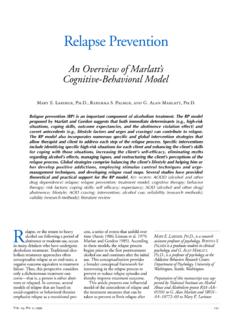
1 Non Traditional Machining Jagadeesha T, Assistant Professor, MED, National Institute of Technology , Calicut Ultrasonic Machining Definition: Ultrasonic Machining is a non-traditional process, in which abrasives contained in a slurry are driven against the work by a tool oscillating at low amplitude (25-100 microns) and high frequency (15-30 kHz). Process: Ultrasonic Machining is a mechanical type non-traditional Machining process. It is employed to machine hard and brittle materials (both electrically conductive and non conductive material) having hardness usually greater than 40 HRC. The process was first developed in 1950s and was originally used for finishing EDM surfaces. In Ultrasonic Machining , tool of desired shape vibrates at Ultrasonic frequency ( 19 to 25 kHz. ) with an amplitude of 15-50 Microns over work piece.
2 Generally tool is pressed down with a feed force F. Between the tool and work, Machining zone is flooded with hard abrasive particles generally in the form of water based slurry. As the tool vibrates over the work piece, abrasive particles acts as indenter and indent both work and tool material . Abrasive particles , as they indent , the work material would remove the material from both tool and work piece. In Ultrasonic Machining material removal is due to crack initiation, propagation and brittle fracture of material. USM is used for Machining hard and brittle materials, which are poor conductors of electricity and thus cannot be processed by Electrochemical Machining ( ECM) or Electro discharge Machining (EDM). The tool in USM is made to vibrate with high frequency on to the work surface in the midst of the flowing slurry.
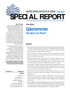
3 The main reason for using Ultrasonic frequency is to provide better performance. Audible frequencies of required intensities would be heard as extremely loud sound and would cause fatigue and even permanent damage to the auditory apparatus. Non Traditional Machining Jagadeesha T, Assistant Professor, MED, National Institute of Technology , Calicut Equipment: Ultrasonic Machining consists of : 1. High Power sine wave generator 2. Magneto-strictive Transducer 3. Tool Holder 4. Tool High power sine wave generator This unit converts low frequency (60 Hz) electrical power to high frequency (20kHz) electrical power. Transducer The high frequency electrical signal is transmitted to traducer which converts it into high frequency low amplitude vibration. Essentially transducer converts electrical energy to mechanical vibration.
4 There are two types of transducer used 1. Piezo electric transducer 2. Magneto-stricitve transducer. Non Traditional Machining Jagadeesha T, Assistant Professor, MED, National Institute of Technology , Calicut Piezo electric transducer: These transducer generate a small electric current when they are compressed. Also when the electric current is passed though crystal it expands. When the current is removed , crystal attains its original size and shape. Such transducers are available up to 900 Watts. Piezo electric crystals have high conversion efficiency of 95%. Magneto-strictive transducer: These also changes its length when subjected to strong magnetic field. These transducer are made of nickel , nickel alloy sheets. Their conversion efficiency is about 20-30%. Such transducers are available up to 2000 Watts.
5 The maximum change in length can be achieved is about 25 microns. Tool holder. OR Horn. The tool holder holds and connects the tool to the transducer. It virtually transmits the energy and in some cases, amplifies the amplitude of vibration. Material of tool should have good acoustic properties, high resistance to fatigue cracking. Due measures should be taken to avoid Ultrasonic welding between transducer and tool holder. Commonly used tool holders are Monel, titanium, stainless steel. Tool holders are more expensive, demand higher operating cost. Tool holder can be classified as : Amplifying Tool Holder Non-Amplifying Tool Holder They give as much as 6 times increased tool motion. It is achieved by stretching and relaxing the tool holder material. MRR = 10 times the non amplifying tool.
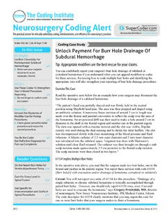
6 Non amplifying tool holders have circular cross section and give same amplitude at both ends. Tool Tools are made of relatively ductile materials like Brass, Stainless steel or Mild steel so that Tool wear rate (TWR) can be minimized. The value of ratio of TWR and MRR depends on kind of abrasive, work material and tool materials. OPERATIONS OF Ultrasonic CUTTING. As the tool vibrates with a specific frequency, an abrasive slurry (usually a mixture of abrasive grains and water of definite proportion) is made to flow through the tool work interface. The impact force arising out of vibration of the tool end and the flow of slurry through the work tool interface actually causes thousands of microscopic abrasive grains to remove the work material by abrasion.
7 Material removal from the hard and brittle materials will be the form of sinking, engraving or any other precision shape. Non Traditional Machining Jagadeesha T, Assistant Professor, MED, National Institute of Technology , Calicut Process parameters 1. Amplitude of vibration ( 15 to 50 microns) 2. Frequency of vibration ( 19 to 25 kHz). 3. Feed force (F) related to tool dimensions 4. Feed pressure 5. Abrasive size 6. Abrasive material ** Al203, SiC, B4C, Boron silicarbide, Diamond. 7. Flow strength of the work material 8. Flow strength of the tool material 9. Contact area of the tool 10. Volume concentration of abrasive in water slurry 11. Tool a. Material of tool b. Shape c. Amplitude of vibration d. Frequency of vibration e. Strength developed in tool 12. Work material a. Material b. Impact strength c.
8 Surface fatigue strength 13. Slurry a. Abrasive hardness, size, shape and quantity of abrasive flow b. Liquid Chemical property, viscosity, flow rate c. Pressure d. Density Process capability 1. Can Machine work piece harder than 40 HRC to 60 HRC like carbides, ceramics, tungsten glass that cannot be machined by conventional methods 2. Tolerance range 7 micron to 25 microns 3. Holes up to 76 micron have been drilled hole depth upto 51mm have been achieved easily. Hole depth of 152mm deep is achieved by special flushing techniques. 4. Aspect ratio 40:1 has been achieved 5. Linear material removal rate to 25mm/min 6. Surface finish micron to micron 7. Non directional surface texture is possible compared to conventional grinding 8. Radial over cut may be as low as to 4 times the mean abrasive grain size.
9 Non Traditional Machining Jagadeesha T, Assistant Professor, MED, National Institute of Technology , Calicut Applications 1. Machining of cavities in electrically non-conductive ceramics 2. Used to machine fragile components in which otherwise the scrap rate is high 3. Used for multistep processing for fabricating silicon nitride (Si3N4) turbine blades 4. Large number of holes of small diameter. 930 holes with has been reported ( Benedict, 1973) using hypodermic needles 5. Used for Machining hard, brittle metallic alloys, semiconductors, glass, ceramics, carbides etc. 6. Used for Machining round, square, irregular shaped holes and surface impressions. 7. Used in Machining of dies for wire drawing, punching and blanking operations 8. USM can perform Machining operations like drilling, grinding and milling operations on all materials which can be treated suitably with abrasives.
10 9. USM has been used for piercing of dies and for parting off and blanking operations. 10. USM enables a dentist to drill a hole of any shape on teeth without any pain 11. Ferrites and steel parts , precision mineral stones can be machined using USM 12. USM can be used to cut industrial diamonds 13. USM is used for grinding Quartz, Glass, ceramics 14. Cutting holes with curved or spiral centre lines and cutting threads in glass and mineral or metallo-ceramics Advantages 1. It can be used machine hard, brittle, fragile and non conductive material 2. No heat is generated in work, therefore no significant changes in physical structure of work material 3. Non-metal (because of the poor electrical conductivity) that cannot be machined by EDM and ECM can very well be machined by USM. 4. It is burr less and distortion less processes.