Transcription of UN1230 5070 user manual - isurplus.com.au
1 Model 5070. GAUSS / TESLA METER. Instruction manual manual UN-01-230. Rev. E, ECO 13096. Item No. 359925. sypris Test & Measurement All rights reserved. This symbol appears on the instrument and probe. It refers the operator to additional information contained in this instruction manual , also identified by the same symbol. NOTICE: See Pages 3-1 and 3-2. for SAFETY. instructions prior to first use ! Table of Contents SECTION-1 INTRODUCTION. Understanding Flux 1-1. Measurement of Flux 1-2. Product 1-5. 1-6. SECTION-2 SPECIFICATIONS. 2-1. Standard Transverse 2-3. Standard Axial 2-4. Optional Probe Extension 2-5. Zero Flux 2-6.
2 SECTION-3 OPERATING INSTRUCTIONS. Operator 3-1. Operating 3-3. Instrument 3-5. 3-7. Power-Up 3-8. Low Battery 3-9. Overrange 3-10. AC or DC Measurement 3-11. UNITS of Measurement 3-12. RANGE 3-13. HOLD Mode 3-15. MIN / MAX Hold 3-16. ZERO 3-17. Automatic ZERO 3-18. manual ZERO 3-20. Sources of Measurement 3-22. More details on AC Mode 3-25. More details on DC Mode 3-26. i 4-1. List of Illustrations Figure 1-1 Flux Lines of a Permanent 1-1. Figure 1-2 Hall 1-3. Figure 1-3 Hall Probe 1-4. Figure 2-1 Standard Transverse 2-3. Figure 2-2 Standard Axial 2-4. Figure 2-3 Optional Probe Extension 2-5. Figure 2-4 Zero Flux 2-6. Figure 3-1 Auxiliary Power Connector 3-1.
3 Figure 3-2 Probe Electrical 3-2. Figure 3-3 Operating 3-3. Figure 3-4 Battery 3-5. Figure 3-5 Probe 3-6. Figure 3-6 Power-Up 3-7. Figure 3-7 Missing Probe 3-8. Figure 3-8 Low Battery 3-10. Figure 3-9 Overrange Indication .. 3-10. Figure 3-10 MODE (AC-DC) 3-11. Figure 3-11 UNITS 3-12. Figure 3-12 RANGE 3-14. Figure 3-13 HOLD 3-16. Figure 3-14 Automatic ZERO 3-19. Figure 3-15 manual ZERO 3-21. Figure 3-16 Probe Output versus Flux 3-23. Figure 3-17 Probe Output versus 3-23. Figure 3-18 Flux Density Variations in a 3-24. Figure 3-19 Low AC Signal 3-25. ii Section 1. Introduction UNDERSTANDING FLUX DENSITY. Magnetic fields surrounding permanent magnets or electrical conductors can be visualized as a collection of magnetic flux lines; lines of force existing in the material that is being subjected to a magnetizing influence.
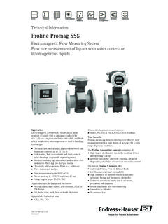
4 Unlike light, which travels away from its source indefinitely, magnetic flux lines must eventually return to the source. Thus all magnetic sources are said to have two poles. Flux lines are said to emanate from the north pole and return to the south pole, as depicted in Figure 1-1. Figure 1-1. Flux Lines of a Permanent Magnet One line of flux in the CGS measurement system is called a 8. maxwell (M), but the weber (W), which is 10 lines, is more commonly used. Flux density, also called magnetic induction, is the number of flux lines passing through a given area. It is commonly assigned the symbol B in scientific documents.
5 In the CGS system a gauss (G) is one line of flux passing through a 1 cm2 area. The more 1-1. INTRODUCTION. commonly used term is the tesla (T), which is 10,000 lines per cm2 . Thus 1 tesla = 10,000 gauss 1 gauss = tesla Magnetic field strength is a measure of force produced by an electric current or a permanent magnet. It is the ability to induce a magnetic field B . It is commonly assigned the symbol H in scientific documents. The unit of H in the CGS system is an oersted (Oe), but the ampere-meter (Am) is more commonly used. The relationship is 1 oersted = ampere-meter 1 ampere-meter = oersted It is important to know that magnetic field strength and magnetic flux density are not the same.
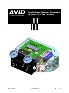
6 Magnetic field strength deals with the physical characteristics of magnetic materials whereas flux density does not. The only time the two are considered equal is in free space (air). Only in free space is the following relationship true: 1 G = 1 Oe = T = Am MEASUREMENT OF FLUX DENSITY. A device commonly used to measure flux density is the Hall generator. A Hall generator is a thin slice of a semiconductor material to which four leads are attached at the midpoint of each edge, as shown in Figure 1-2. 1-2. INTRODUCTION. Figure 1-2. Hall Generator A constant current (Ic) is forced through the material. In a zero magnetic field there is no voltage difference between the other two edges.
7 When flux lines pass through the material the path of the current bends closer to one edge, creating a voltage difference known as the Hall voltage (Vh). In an ideal Hall generator there is a linear relationship between the number of flux lines passing through the material (flux density) and the Hall voltage. The Hall voltage is also a function of the direction in which the flux lines pass through the material, producing a positive voltage in one direction and a negative voltage in the other. If the same number of flux lines pass through the material in either direction, the net result is zero volts. This sensitivity to flux direction makes it possible to measure both static (dc) and alternating (ac).
8 Magnetic fields. The Hall voltage is also a function of the angle at which the flux lines pass through the material. The greatest Hall voltage occurs when the flux lines pass perpendicularly through the material. Otherwise the output is related to the cosine of the difference between 90 and the actual angle. 1-3. INTRODUCTION. The sensitive area of the Hall generator is generally defined as the largest circular area within the actual slice of the material. This active area can range in size from mm ( ) to 19. mm ( ) in diameter. Often the Hall generator assembly is too fragile to use by itself so it is often mounted in a protective tube and terminated with a flexible cable and a connector.
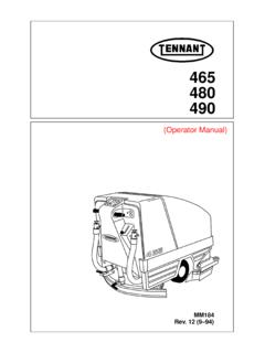
9 This assembly, known as a Hall probe, is generally provided in two configurations: Figure 1-3. Hall Probe Configurations In transverse probes the Hall generator is mounted in a thin, flat stem whereas in axial probes the Hall generator is mounted in a cylindrical stem. The axis of sensitivity is the primary difference, as shown by B in Figure 1-3. Generally transverse probes are used to make measurements between two magnetic poles such as those in audio speakers, electric motors and imaging machines. Axial probes are often used to measure the magnetic field along the axis of a coil, solenoid or traveling wave tube. Either probe can be used where there are few physical space limitations, such as in geomagnetic or electromagnetic interference surveys.
10 1-4. INTRODUCTION. Handle the Hall probe with care. Do not bend the stem or apply pressure to the probe tip as damage may result. Use the protective cover when the probe is not in use. PRODUCT DESCRIPTION. The MODEL 5070 GAUSS / TESLAMETER is a portable instrument that utilizes a Hall probe to measure magnetic flux density in terms of gauss, tesla or ampere-meter. The measurement range is from mT ( G or kAm) to ( kG or 1591 kAm). The instrument is capable of measuring static (dc) magnetic fields and alternating (ac) fields. The MODEL 5070 consists of a palm-sized meter and various detachable Hall probes. The meter operates on standard 9 volt alkaline batteries or can be operated with an external ac-to-dc power supply.