Transcription of UNDERSTANDING AND CONTROLLING COMMON …
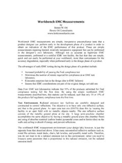
1 Henry W. OttHOCELECTROMAGNETICCOMPATIBILITY2001 ByHenry W. OttHenry Ott ConsultantsLivingston, NJ 07039(973) AND CONTROLLINGCOMMON-MODE EMISSIONSIN HIGH-POWER ELECTRONICSPage 1 Henry W. OttHOCELECTROMAGNETICCOMPATIBILITYTHE BASIC PROBLEM!Switching Power Supplies and Variable Speed Motor DrivesProduce Large Noise Currents Which are Conducted Out tothe Load, as Well as Conducted Back to The Power Source!These COMMON -Mode Noise Currents are the Cause of: Low Frequency Conducted Emission, and High Frequency Radiated Emission!Once One Has an UNDERSTANDING of the Noise Source andCoupling Mechanism, a Solution Can be Determined!
2 Power Line Filters in Combination With Proper Load SideFiltering, Grounding, and/or Shielding Will Usually SolveMost COMMON -Mode Emission 22001 Henry W. OttHOCELECTROMAGNETICCOMPATIBILITYBASIC PRINCIPLE OF EMCR eturn Current to its Source as Locallyand Compactly as PossiblePage 32001 Minimize the Loop Area Henry W. OttHOCELECTROMAGNETICCOMPATIBILITYCOMMON -MODE & DIFFERENTIAL MODE NOISE!Differential-Mode Noise Involves the NormalOperation of the Circuit Currents Flowing AroundLoops Is Documented Schematics PCB Layout Wiring Diagrams Is Easy to Understand! COMMON -Mode Noise Does Not Relate to theNormal Operation of theCircuit Involves Parasitics Currents Flow Around LoopsUsually Involving ParasiticCapacitance Is Not Documented Is More Difficult toUnderstand The Noise Source andCurrent Path Must First beVisualized and UnderstoodBefore a Solution Can beDeterminedPage 42001 Henry W.
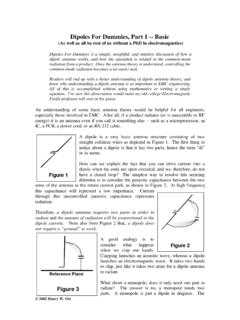
3 OttHOCELECTROMAGNETICCOMPATIBILITYRADIAT ION MECHANISMS2001 Page 5 DIFFERENTIAL-MODERADIATIONS ignalGroundI0 PCBR adiatedEmissionE = K1 f2 A I0 Gnd PlaneOr GridVNPWBIcmI/O CableGnd WireCOMMON-MODERADIATIONR adiatedEmissionE=K2 f L Icm Henry W. OttHOCELECTROMAGNETICCOMPATIBILITYBASIC ANTENNA TYPESPage 62001 Antenna TypeRadiation MechanismElectromagnetic FieldLoopDifferential-ModeMagnetic FieldDipoleCommon-ModeElectric Field Henry W. OttHOCELECTROMAGNETICCOMPATIBILITYRADIAT ED VERSUS CONDUCTED C-M EMISSIONPage 72001 ProductLoadorLISNVCMICMR adiation DirectlyProportional to C-MCurrentCommon-ModeNoise SourceVCMC ommon-ModeCurrent Convertedto a C-M Voltage bythe Load or LISNI mpedanceParasiticCapacitanceICM Henry W.
4 OttHOCELECTROMAGNETICCOMPATIBILITYEMC REGULATIONS PERTAINING TO C-MEMISSIONS!North America (FCC/Industry Canada)!European Union (EU)!Military (MIL-STD)Page 82001 Henry W. OttHOCELECTROMAGNETICCOMPATIBILITY1 MHz10 MHz1,000 MHzFrequencyFREQUENCY RANGEPage 92001100 MHzEU Radiated MHzEU Conducted EmissionFCC Radiated EmissionFCC Conducted Emission30 MHzRadiatedConducted450 kHz150 kHzEUONLYMIL-STD 461D, CE102 Conducted Emission10 kHzMIL-STD 461D, RE102 Radiated Emission40 GHz18 GHzMIL-STD 461D, RE102 For Some Henry W. OttHOCELECTROMAGNETICCOMPATIBILITY10 kHz100 kHz1 MHz10 MHz100 MHzFrequency405060708090dB V2001 Page 10 CISPR B LimitFCC B Limit100 FCC A LimitMIL-STD 461D, CE 102 Limit (115 V)CISPR A LimitCOMPARISON OF CONDUCTED EMISSION LIMITS Henry W.
5 OttHOCELECTROMAGNETICCOMPATIBILITYHOW MUCH C-M CURRENT IS A PROBLEM(Based on FCC Requirements)Page 112001 FrequencyClass AClass B< MHz *40 uA10 - 30 MHz*120 uA10 uA30 MHz**24 uA8 uA50 MHz**15 uA5uA100 MHz** uA* Based on Conducted Emission Limits** Based on Radiated Emission Limits Henry W. OttHOCELECTROMAGNETICCOMPATIBILITYTHE BASIC C-M PROBLEM2001 Page 12 PowerSourceLoadPower Supply orMotor DriveLargedV/dtSwitchRadiationRadiationC -M CurrentC-M CurrentC-M CurrentGround** Any of the parasitic capacitance's could be a metallic connection to ground Henry W. OttHOCELECTROMAGNETICCOMPATIBILITY C-M CURRENT LOOPS2001 Page 13 PowerSourceLoadPower Supply orMotor DriveLargedV/dtSwitchInput LoopOutput LoopOverall (Input-Output Loop)GroundThere Are Three Possible Loops to be Concerned With Henry W.
6 OttHOCELECTROMAGNETICCOMPATIBILITYTHE INVISIBLE SCHEMATIC!Consists of: the dV/dt Generator, and the Parasitic Capacitance!You Should be Able to Find and VisualizeThese Components!Once the Invisible Schematic Componentsare Identified, the Required ControlTechniques Become Fairly Straightforwardand Obvious. They are not Black Magic. Page 142001 Henry W. OttHOCELECTROMAGNETICCOMPATIBILITYC-M EMISSION CONTROL TECHNIQUES!Find a Way to: Reduce the Magnitude of the Source (dV/dt) Reduce the Parasitic Capacitance Reduce the C-M Current ( Filtering) Return the C-M Current Through a SmallLoop That Does Not Involve the ExternalGround Path (Small Loop Area)!
7 Usually The Closer You Can Get The Control tothe Noise Source (the dV/dt Generator*) theMore Effective the TechniquePage 152001* Usually the Switching Transistors Henry W. OttHOCELECTROMAGNETICCOMPATIBILITYPage 161998 Switching TransistorII50-500 pFParasiticCapacitanceDCOutputHeatSinkII GroundI = C-M Noise CurrentIHotINeutralACInputCISWITCHING POWER SUPPLYCONDUCTED EMISSION, COMMON -MODE Henry W. OttHOCELECTROMAGNETICCOMPATIBILITY BASIC IGBT MOTOR DRIVE2001 Page 17 PowerSourceMotor orInductiveLoadGroundIGBT Drive CircuitMotor HousingUsually GroundedICMICM Henry W. OttHOCELECTROMAGNETICCOMPATIBILITYBASIC SOLUTIONS TO THE C-M PROBLEM!
8 Minimize the dV/dt!Reduce the Parasitic Capacitance!Use Filtering To Reduce the C-M Current on the Cable!Use Grounding To Return the C-M Current!Use Shielding To Return the C-M Current To Reduce the Parasitic CapacitancePage 182001 Henry W. OttHOCELECTROMAGNETICCOMPATIBILITY BASIC IGBT MOTOR DRIVE2001 Page 19 PowerSourceMotorGroundIGBT Drive CircuitIIdV/dtNet C-M Cable CurrentEqual to I Henry W. OttHOCELECTROMAGNETICCOMPATIBILITYTHE BASIC IGBT MOTOR DRIVE PROBLEM(LOAD SIDE C-M CURRENT)!The IGBT Switches are the C- M Voltage Source!This Causes a Large Current (dI/dt) to Flow On the OutputLeads to the Motor!The Low Frequency Current Goes Through the MotorWindings as Intended!
9 The High Frequency Current, However, CapacitivelyCouples to The Motor Housing (Which is Usually Grounded)!The Return Current Path Can Vary But Usually FlowsThrough the External Ground May Capacitively Couple Back to the IGBT Drive (AsShown in the Previous Slide) Or in Some Cases May Flow All the Way Back to thePower Source and From There Back to the Switches!In All Cases, However, The Problem Arises Because of theCapacitance Between the Motor Windings and the HousingPage 202001 Henry W. OttHOCELECTROMAGNETICCOMPATIBILITYPOSSIB LE SOLUTIONS!Power Input Side of the Switch Use a Power Line Filter!Output (Load) Side of Switch Use Grounding or Shielding To Return C-M Current Without Using the ExternalGround Path Use Filtering To Return the C-M Current Locally to the Switch Reduce the dV/dt or the Motor Capacitance (Not UsuallyPractical)!
10 Remember the Switch is the Source of the C-M Voltage and theMotor Capacitance Provides the C-M Current Return PathPage 212001 Henry W. OttHOCELECTROMAGNETICCOMPATIBILITY GROUND WIRE FROM MOTOR HOUSING TOSWITCH COMMON2001 Page 22 PowerSourceMotorGroundGround Wire(Routed WithOutput Conductor)IThis is the Ideal Solution But May Be Difficult to ImplementEither the Motor Housing Must be Floating (as shown), or the Switch COMMON Must be Connected to GroundAlternative Approach: Add a Capacitor in Series With the Ground Wire to Provide an AC Connection OnlyCapacitor Value Limited by Leakage Current Requirements. Therefore, Not Very Effective at Low FrequenciesNet C-M Cable CurrentEqual to Zero Henry W.