Transcription of UNDERSTANDING ASCE-10 COMPRESSION AND …
1 UNDERSTANDING ASCE-10 COMPRESSION AND TENSION DESIGN IN PLS-TOWER Author: Alberto Le n Zuluaga G mez, BS in Civil Engineering, Universidad Nacional de Colombia, Colombia and MS in Structural Engineering and Civil Construction, Universidade de Bras lia, Brazil. Company: Interconexi n El ctrica - ISA. ( ) E-Mail: ABSTRACT This paper has the objective of showing through two simple flow charts, how PLS-Tower develops the COMPRESSION and tension design according to the ASCE-10 requirements. It is intended to present information about the design results that the program performs internally, and do so in a simpler, more understandable form. The information contained in this article only applies when dealing with ASCE-10 requirements; however, it could be easily extrapolated to other design codes that the PLS-Tower supports, like AS-3995, Canada S37, PN-90/B-03200, etc.
2 NOTATION Variable Short definition a Width of single angle short leg [in] Member effective area [in ] Gross cross-sectional area [in ] Net cross-sectional area [in ] At Minimum net area in tension from the hole to the toe of the angle perpendicular to the line of force [in ] Minimum net area in shear [in ] b Width of single angle long leg [in] Connection bearing capacity [kips] 1 Eccentricity code 2 Restrain code Column slenderness ratio COMPRESSION capacity based on member slenderness L/r column slenderness ratio [kips] Angle legs connection code (Both, Long only or Short only) Nominal diameter of bolt [in] Diameter of attachment hole [in] End distance of bolt hole [in] Modulus of elasticity of steel [ksi] f Short edge distance of bolt hole [in] Design axial compressive stress [ksi] Critical stress for local buckling [ksi] Design axial tensile stress [ksi] Specified minimum tensile strength [ksi] Variable Short definition Specified minimum yield stress [ksi] Effective length factor Unbraced length of member [in] Unbraced member length about its local x-axis [in] Unbraced member length about it local y-axis [in] Unbraced member length about it local z-axis [in]
3 Number of angles in cross section Number of bolts in end connection Number of bearing areas per bolt Number of holes to be deducted Number of shear planes per bolt Tension capacity based on net section [kips] Member radii of gyration [in] Connection block shear capacity [kips] Connection rupture capacity [kips] Connection end, edge or spacing distance capacity [kips] Alternate unbraced length ratio for crossing diagonals Member unbraced length ratio for its local x-axis Member unbraced length ratio for its local y-axis Member unbraced length ratio for its local z-axis Member radii of gyration for its local x-axis [in] Member radii of gyration for its local y-axis [in] Member radii of gyration for its local z-axis [in] Bolt spacing [in] Connection shear capacity [kips] Thickness of element [in] Design shear capacity of one bolt [ksi] Flat-width of element [in] / Width to thickness ratio Unit factor ( for in ksi and for in MPa) %ratio Absolute value of the tension force in the supporting member divided by the force in the compressed member DISCLAIMER The author will be not responsible for any information contained in this article.
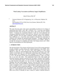
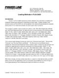
4 The conclusions and recommendations should be used by an experienced engineer, and Licensee assumes all responsibility for the design assumptions and results. Figure 1. COMPRESSION design flow chart Figure 2. Tension design flow chart Members connected by both legs, (CL=Both): Members connected by long leg, (CL=Long Only): t Members connected by short leg, (CL=Short Only): 1 (number of angles in cross section) if = 1 or 2, or / 2 if = 4 /1 / 2 1 / Tension capacity based on net section, Connection shear capacity, Connection bearing capacity, Connection rupture capacity, CAPACITY IN TENSION 1 2 REFERENCES (1) TOWER Version Manual.
5 Power Line System, Inc . 2012. (2) ASCE 10 (1997). Design of Latticed Steel Transmission Structures. American Society of Civil Engineers. Reston, Va.