Transcription of Understanding Bend Tests - MCAA
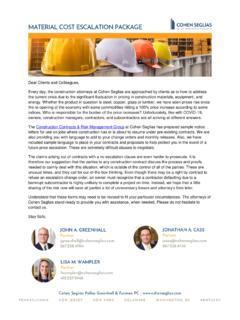
1 Understanding Bend Tests Many welding codes require bend Tests as part of the testing required to qualify welders and welding procedures specifications (WPSs). The concept of a bend test for welds is simple: two plates are welded together and a flat strap of metal is cut from the welded plates. Next, the flat strap of a prescribed size is bent into a U-shape, stretching the material on the outer surface of the "U," while compressing the material on the inside surface. The purpose is to make certain the weld and the base metal are properly fused, and that the weld metal and the heat affected zone (HAZ) have appropriate mechanical properties (Figure 1).
2 Figure 1: In a bend test, a flat strap of metal is bent into a U-shape, stretching the material on the outer surface of the "U," while compressing the material on the inside surface. Although bend Tests appear to be simple, any number of things can cause good welding procedure specifications or good welders to fail. The person responsible for accepting or rejecting test results must understand those factors, and know how to correct for any that are causing inappropriate failure. Bend specimens have been called "a poor man's tensile test." Although it will not show the quantitative values associated with a tensile test, a bend test will demonstrate both the quality of the weld and its overall ductility.
3 Usually, bend Tests are designed so that the outer surface of the specimen is stretched to a ductility level that approximates the minimum percent elongation required in a tensile test. When defects exist in materials strained to these limits, the material tears locally. When tearing exceeds a specific limit, the specimen fails. Direction of rolling Steel is not fully isotropic, and ductility is sensitive to rolling direction. When steel is strained parallel to the direction of rolling, the highest values of elongation are obtained. When it is stretched perpendicular to the rolling direction, ductility is reduced.
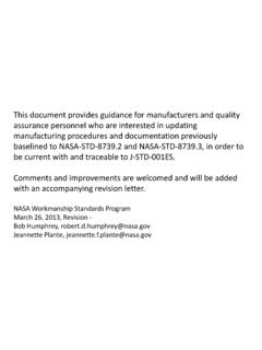
4 The poorest ductility usually is measured in the through- thickness direction. Qualification test plates can be prepared with the weld groove preparation parallel to the direction of rolling. The length of the bend specimens extracted from such a test plate will be perpendicular to the rolling direction (Figure 2). This means when the specimen is bent, straining is perpendicular to the rolling direction and the transverse ductility affects the test. Sometimes specimens break near the interface of the weld and base metal, with the fracture revealing a fibrous, "woody" appearance. Failures like these have nothing to do with either welder skill or the suitability of the WPS.
5 However, neither will be qualified until these testing problems are overcome. Figure 2: Qualification test plates prepared with the weld groove preparation parallel to the direction of rolling. Fortunately, the solution is simple change the orientation of the weld seam so that the weld axis is perpendicular to the rolling direction (Figure 3). Figure 3: Re-orient the weld seam so that the weld axis is perpendicular to the rolling direction. Matched Mechanical Properties When a transverse bend specimen is tested, the base metal, the HAZ and the weld metal are all stressed.
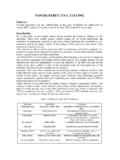
6 The response to this stress is strain, and the degree of straining depends on the yield strength. To obtain relatively uniform straining across these three zones, the three materials must have similar deformation properties. Otherwise, straining can be concentrated in one material, causing the bend specimen to fail. When the strength of the weld is much greater than the base metal, the bending strains concentrate in the base metal and the HAZ. This in turn can create a distinct flat spot in the weld at center of the bend specimen (Figure 4). While a welder can't be blamed for this problem, the WPS should be questioned.
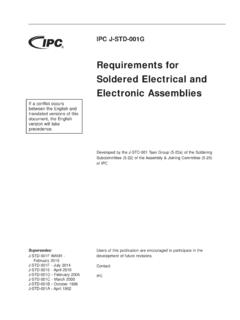
7 Since overmatching the weld metal to the base metal is generally undesirable, the individuals responsible for accepting or rejecting the test results should investigate the reason for the strength overmatch. Figure 4: A flat spot can appear in the center of the length of the bend specimen when the strength of the weld exceeds than that of the base metal When the base metal is significantly stronger than the weld metal, the bending strains concentrate in the weld. A peak may then occur in the bend specimen, creating a so-called "dog house" look (Figure 5). The base metal portion of the specimen is essentially flat and unstrained, while the weld is stretched beyond its capacity until it breaks.
8 Figure 5: When the base metal is significantly stronger than the weld metal, the bending strains concentrate in the weld creating a "dog house" look. It is not unusual for a base metal to exceed the weld metal's strength, since base metal classifications are usually based on the minimum specified yield strengths. The actual yield strengths can be much higher than the specified minimums. Thus, the weld metal that will theoretically match the base metal in strength may in reality undermatch the base metal's actual strength. Although this situation usually poses no problem, the inelastic ( , post-yield) behavior may be different.
9 That is why it is important to check the potential effect on the final product or structure. When the properties of the base metal and weld metal are significantly different, some codes permit the use of a longitudinal bend specimen (Figure 6). In this configuration, the base metal, HAZ and weld metal are all subjected to the same strain. Tests performed in this manner measure both ductility and soundness, and the strains are not inappropriately concentrated in any localized material. Figure 6: When the properties of the base metal and weld metal are significantly different, some codes permit the use of a longitudinal bend specimen.
10 Notches Notches that are perpendicular to stress fields create localized stress concentrations where cracks can initiate. In a bend specimen, the stress field is parallel to the length of the bar so notches perpendicular to this length create stress concentrations. When such notches exist, bend specimens may fail simply because the specimen is poorly prepared (Figure 7). Figure 7: Notches that are perpendicular to stress fields create localized stress concentrations where cracks may occur. Generally, weld reinforcements are removed from bend specimens before testing.