Transcription of Understanding electric arc furnace operations for …
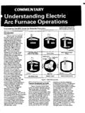
1 A .. ~ 0 13, . NO. 2, 1987 published by the Center for Metals production - An EPRl Sponsored R&D Applications Center Understanding electric Arc furnace operations For Steel production Introduction silicon and the burning of natural gas The use of electric arc furnaces (EAF). for steelmaking has grown dramati- Energy Needs with oxy-fuel burners. About 53% of the cally in the last decade in the United Furnaces are often classified by power total energy leaves the furnace in the States. In 1975 electric furnaces ac- requirement levels. A scale indicating liquid steel, while the remainder is lost counted for 20% of the steel produced power classification ranging from ultra- to slag, waste gas, or cooling. in the ; by 1985 this figure had high-power (UHP), withover 700 kVA Typical tap-to-tap time has decreased grown to 34%. electric furnaces range per ton, downto low-power, with less from over 2 hours in 1960 to 70-80.
2 In capacity from a few tons to as many than 200 kVA per ton, is shown in minutes today. Primarily responsible are as 400, and a steelmaking shop can Figure 1 along with some representa- UHP furnaces, oxy-fuel burners, water- have a single furnace or up to three tive furnaces. cooled side panels (which allow for or four. In brief, these furnaces melt higher power after the steel is molten), steel by applyingan AC current to a KVA EXAMPLES. foamy slag practices (which also permit steel scrap charge by means of graphite PER higher power), and ladle metallurgy TON. electrodes. It requires about 500 kwh (which removes the refining function IMX) - of electricity to produce a ton of steel; ULTRA-HIGH. from the furnace and shifts it to a ladle 900 - into which the molten metal is poured). consequently, these furnaces use a 800 - ..~.. tremendous quantity of electricity. Trans- 0 CHAPARRAL.
3 0 BETHLEHEM(JOHNSTOWNI. ~. former loads mayreach 120 MVA. 700 . Chemical Ekctricol The melting process involves the use 600 - 0 INLAND. HIGH. of large quantitiesof energy in a short 500 - 0 LUKENS n . 0 ATUNTIC STEEL. time (1-2 hr) andin some instances the 400 - process has caused disturbances in 300 - MEDIUM ARMCO (KANSAS CITY). power grids. These disturbances have usually been characterized as flicker - ~. LOW 0 LTV(CLEVELAND). - brief irregularitiesin voltage a frac- 100 . tion of the60 Hz cycle inlength, and I. harmonics - irregularities that tend to Figure 1. occur in a pattern repetitive to the 60 EAF Power Classifications Hz cycle. The featuresof electric arc furnaces were describedin a CMPTech- It is important to consider the energy Commentary on electric Arc Furnaces balance for a typical modem EAF: The (Vol. 1, No. 3, 1985). The purposeof energy diagram shownin Figure 2 indi- the present Techcommentary is to cates that70% of the total energy is give utilities and steel mills a better electrical, the remainder being chemical Understanding of electric furnaces from energy arising from the oxidation of an electrical viewpoint.)
4 Elements such as carbon, iron, and Figure 2. Energy Patterns in an electric furnace Typical Arc ignition peGiod (start of power supply ) Boring period Molten metal period Steelmaking Cycle A typical heat cycle appearsin Figure 3. To achieve meltdown as quickly as possible, electrodes are initially lowered to a point above the material, the Conditions of current is initiated, and the electrodes furnace bore through the scrap to form a pool of liquid metal. The scrap itself protects the furnace lining from the high- intensity arc. Subsequently, the arc is I. lengthened by increasing the voltage to maximum power. Most modem fur- To protect the furr naces are equipped with water-cooled roof from arc by supplying high power from arc soot 2. To stabilize the arc and increasing the boring panels in the upper halfof the sidewall, 3. To rapidly submerge the speed Operating 2. To increase the boring rather than refractories, which allows objectives electrode tip into scrap diameter for longer arcs and higher energy input into the the final stage, when there is a nearly complete metal I I I I.
5 I. pool, the arcis shortened to reduce I 11 Optimum current a OP. radiation heat losses and to avoid refrac- tory damage and hot spots. After melt dawn, oxygen usually isin- jected to oxidize the carbon in the steel a 00. Characteristic u 80. or the charged carbon. This process is curve of arc power 2 60 Is Short- 60. an important source of energy; the car- ? 40 c~rcuiting 40. current 40. 20 20. bon monoxide that evolves helps mini- mize the absorption of nitrogen and . 0 40 80 I20 160 0 40 80 120 160. ArcCurrent Io %. flushes hydrogen out of the metal. It also foams the slag, which helps mini- mize heatloss. To be judged by 1. The rate of lowering TO be judg A? t the position the electrode consumption (kW. Criteria for where the 2. The lowered position of the boring period operation of electrode tip is the electrode submerged for furnace T about Detailed Electrical I 1 I. - Courtesy of the Iron and Steel Society.)
6 Inc. - electric furnace Steelmaking 1985. I. Operation Figure 3 SteelMeltingCycle After an electric furnaceis charged with tinguished by a minor overshoot in an early meltdown, and they occur at vary- scrap and the roofis in place, the electrode regulator or by physical move-ing frequencies. operator lowers the electrodes, each ment of the the scrap melts, Many attempts have been madeto of which has its own regulator and it can often shift and fall away from establish the human eye's reaction to mechanical drive. The electrodes are an electrode- extinguishing the arc, the flickerof a lamp. That these endeav- connected to the furnace transformer s or against theelectrode- possibly ors have not exactly confirmed one secondary delta winding, which may breaking it. another is shownin Figure 4 (from Arc be rated from;bout 600 to 850 volts. Because of thephysical movement furnace Power Delivery ), where per- No current flows when the first elec- and settlingof the scrap, wide excur- ception is measured while disturbance trode contacts scrap, but a line-to-line sions can take place on a random basisvoltage and frequency are varied.
7 Eye path through the scrap and an arc are in the secondary circuit. The abrupt response to disturbancesin the 5-10 Hz established when the second electrode initiation and interruption of current range did seem to be greatest in all completes the circuit. The regulators flow provides a source of harmonic the studies. for each of thesetwo electrodes then currents and causes considerable distur- Generation of harmonics may result in signal the drives to raise the elec- bance to high-impedance circuits.( A b o u t further flicker problems, and equip- trodes until the selected current-voltage 75% of the total impedanceis inthe ment on the power system may also ratio for the arcis achieved. Initiation secondary circuit.) Voltage and current be damaged. If static capacitors are to of the third arc depends on the scrap's waves deviate considerably from sym- be used to improve the power factor, location, whichis unpredictable, hence metrical sinusoidal patterns, but they an analysisto ensure that resonance the duration of the unbalance is short do not attain full rectangular shape, does not exist at any of the harmonic but random.
8 While the scrap is still according to findingsin the CMP report, frequencies should be made. Harmon- unmelted, the arc may easily be ex- Arc furnace Power Delivery Scoping Study. ' Disturbances are worst during a full heat. Thisis generally uneconomi- .mation Meltdown-heating period Main melting period Meltdown period cal due to oxidation losses and the need to open the furnace for several Tapping spout separate charges, which results inloss of both time and heat. Noris the use of .. large heavy scrap alone large piece might protrude and interfere with roof closure or require placement .. by magnet, a process which takes time. The furnace operator therefore tries to blend several types of available scrap to suit his needs. It is beneficialto arrange the heavier pieces near the lid baih bottom of the charge. After about20. minutes of operation, dependingon 'bottom Since the arc is surrounded 1.
9 To reduce the local 1. To reduce the heat radiation withsolid materials, the damages near hot spots onto the lining as well as available power and other practices, the therrnol conductivity Of on lining minimize hat spot domoge the electrodes will have opened some arc power is a maxlmum. 2. To rapidly melt the 2. To rapidly increase the Therefore, rapid and uniform remaining scrap temperature of molten voids, and cave-ins can occur. If large steel to the appropriate melting should be planned by supplying the maximum value for refining pieces of scrap are on top of the power that the facilities permit pile, they can possibly slide into and break an electrode. It is generally be- lieved that light, uniform scrap produces a smoother meltdown than does large la heavy scrap. However, this is not al- )P. I20. I4O 1 ! ways the case. If heavy scrap is is 3 160. charged, full power canbe applied.
10 If all the scrapis light, on full power the electrodes may bore through, damag- ing the furnace bottom before a suffi- cient pool of liquid metal has formed. Generally, the initial period of melting causes the most electrical disturbances. As the scrap temperature begins to rise, jowr 1. Variation of arc impedance 1. Power consumption (kwh) Power consumption (kwh) a liquid pool forms, and disturbances lfter 2. Therate of the F c e 2. Melting Conditions of begin to diminish. This is generally about temperature (IPB) scrop 3. Powerconsumption (kwh) 10 minutes or so after power-on and can vary depending on power levels and shop practices. Borderlines of flicker per perceptibility for incandescent light bulbs under laboratoryconditions (1-Common- wealth Edison. 12OV. 25 + 4 0 + 6OW; 2-Japan. lOOV, Melt Down 60W; 3-Schwabe. 120V. 60W; 4-Carjell. 220V, 6OW; ics contributeto wave distortion and 5-Wasowsk~,220V, 40W; 6-Kendal1, 230'4 60W; 7-UIE, Heating steel scrapto approximately 230V, 60W; sinusoidal wave; 8-UIE, 230V, 60W.)
