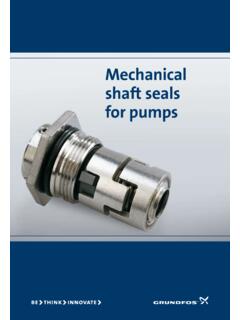
Transcription of UNDERSTANDING MECHANICAL SEALS
1 UNDERSTANDING . MECHANICAL SEALS . INTRODUCTION. Since their inception, MECHANICAL SEALS have carried with them a mystique of Gee Whiz , bizarre, physics defying properties that have baffled the untrained observer. But that impression is really misplaced. MECHANICAL SEALS are not magic by any means and actually perform well within the realm of easy to understand principles of physics and hydraulics. MECHANICAL SEALS are simply another means of controlling leakage of a process where other means are deemed to be less capable of performing the task adequately. For the purposes of this discussion, consider that a MECHANICAL seal will out-perform common types of packing. As MECHANICAL SEALS can be used to seal a myriad of different products on an equally vast array of equipment, we will be primarily focusing on the use of MECHANICAL SEALS on rotating shaft pumps. Since our subject is dealing with pumps, let's first explore a basic UNDERSTANDING of the need to seal a process liquid in a centrifugal pump.
2 CENTRIFUGAL PUMPS. A centrifugal pump is simply a shaft, suspended on bearings with an impeller attached to one end. The impeller is encased in a housing that is filled with a liquid. As the shaft is rotated, centrifugal force expels the liquid out through an orifice, where it is typically piped into a process or another collection point. As the expelled liquid exits the case, additional liquid is added to the case so that a flow develops. That is basically how a centrifugal pump works. The next slide shows a photograph of a typical End Suction Centrifugal Pump . PUMP SHAFT. IMPELLER BEARINGS. A LIQUID IS SUPPLIED TO THE. PUMP SUCTION . CENTRIFUGAL FORCE EXPELS THE. LIQUID OUT FROM THE IMPELLER. AS THE PUMP SHAFT ROTATES. CENTRIFUGAL PUMPS. The force of the expelled liquid creates pressure. This liquid under pressure will seek areas of lower pressure. This is a known physical principle of hydraulics. Some form of seal must be applied to keep liquid from leaking around the shaft at the point where it enters the case to drive the impeller.
3 This is where our MECHANICAL seal comes into play. Take a look at the same pump again. Can you see the MECHANICAL seal behind the impeller? SEAL TYPE. The MECHANICAL seal shown in the pump photograph is a Type 1 MECHANICAL seal. Probably the most widely recognized and also most common MECHANICAL seal used in general service, low pressure applications. At Utex, we refer to this type as RS-1. The assembly shown in the pump is configured with a ceramic O-ring type stationary seat and is also equipped with a set screw collar . SEALING THE LIQUID. MECHANICAL SEALS were originally designed to lend a greater sealing capability than could be achieved using common packing. Before the advent of MECHANICAL SEALS , pump users relied primarily on rope or braided style packing to achieve a seal around the shaft. A series of pieces or rings were installed into the pump stuffing box and they were compressed tightly so that they created a difficult leak path for the liquid to negotiate in order to leak to atmosphere.
4 SEALING THE LIQUID. Early packing styles did not seal very well. In fact, until recently, braided packing styles required varying amounts of leakage for lubrication. If leakage was not permitted to occur, the packing would literally burn up and often cause severe damage to the pump shaft. Even with adequate leakage for lubrication, pump shaft wear was a commonly expected occurrence and as the shaft wore it would in turn, cause poor shaft packing life. As leakage becomes more excessive, the gland is tightened to reduce leakage. SEALING THE LIQUID. With the introduction of MECHANICAL SEALS , this leakage could be controlled to a much greater degree. Let's look at the same pump with a MECHANICAL seal installed. Note that the seal shown is an RS-1 with O- Ring type stationary and a set screw collar. SEALING THE LIQUID. You have probably taken notice of the illustration showing minor leakage to atmosphere. It is appropriate to point out at this time.
5 LESSON NUMBER ONE. ALL. MECHANICAL SEALS . LEAK.. SEALING THE LIQUID. It is a fact, all MECHANICAL SEALS leak. Like packing, the MECHANICAL seal faces must also be lubricated. With proper application and design however, the leakage is so minute that actual droplets of liquid are not detected. Instead, the lubricating liquid will vaporize as it crosses the seal faces and the leakage is a gas or vapor. Since we are discussing the sealing of the liquid at the faces, let's take a look at the sealing points of a typical MECHANICAL seal. Again, viewing the same pump and seal, note that there are four sealing points to consider. The seal gland to the stuffing box of the stationary Sealing on the shaft And finally, the seal faces BRIEF DISCUSSION. ABOUT. MECHANICAL SEAL. FACE DYNAMICS. FACE FLATNESS. The MECHANICAL seal faces are obviously the most critical sealing point of a MECHANICAL seal assembly. Although the faces can be manufactured from a myriad of different materials, one is typically carbon, while the other is usually a hard material.
6 ( Alox (Aluminum Oxide Ceramic), Tungsten Carbide, Silicon Carbide, etc.). In order for a seal to be achieved, the faces must be very flat. This is achieved by machining the faces, then lapping them to a fine finish. Flatness is measured in Light Bands . After lapping, the faces are placed on an Optical Flat , a clear glass surface where a monochromatic light is shined on the face. This single wavelength light will produce an image of rings or lines on the face. Each ring/line is One Light Band . Each light band is equivalent to .000011 or eleven millionths of an inch. This refers to the variations in the surface of the face. On most face materials, one light band is Utex's standard. FACE FLATNESS. This illustration shows a face being inspected on an Optical Flat. Take notice of the light bands that are visible on the reflection of the face. Laying a straight edge on a tangent to the inside circumference of the face, how many light bands are crossed?
7 Optically Flat Faces 100 psi Rotary Stationary Face Face 0 psi FACE FLATNESS. As was stated earlier, it is hoped that the application and design of the MECHANICAL seal is suited for the service. If so, there is leakage of only vapor through the seal faces. Pressure Drop & Vaporization Liquid 100 psi Liquid + Vapor 50 psi Vapor + Liquid 25 psi Vapor 0 psi TYPES OF. MECHANICAL SEALS . SEAL TYPES. There are obviously many different types and configurations of MECHANICAL SEALS . Shaft mounted and cartridge, balanced and unbalanced, pusher and non- pusher, single and multiple, etc., etc. Here we will examine the basic differences without going into a great detail. SEAL TYPES. First, let us examine shaft mounted vs. cartridge. A shaft mounted seal requires the pump user or assembler to actually install individual seal components into the equipment. Let's look at the installation of the RS-1 that we were looking at previously. The stationary seat must be inserted into the seal gland.
8 The seal assembly is slipped onto the pump shaft and the set screws tightened in the correct position to insure proper installed length of the assembly. The gland is tightened evenly so that the seal is compressed to it's recommended length. SEAL TYPES. A cartridge type MECHANICAL seal is a pre-assembled package of seal components making installation much easier with fewer points for potential installation errors to occur. The assembly is pre-set so that no installed length calculations must be performed for determining where to set the seal. This pre-set is achieved by the use of set tabs that are removed once the seal is installed and the pump assembled. Although the assembly The same four sealing may look a little points exist here. menacing, it is basically Seal Gland Gasket no different than a shaft mounted arrangement as far as sealing Stationary O-ring components and sealing points are concerned. Shaft/Sleeve O-ring One additional sealing Seal Faces point exists in this particular cartridge The set tabs are assembly.
9 Have you removed after found it? installation. SEAL TYPES. Remember the number of steps involved in installing the shaft mounted seal. Now let's look at installing the cartridge seal that we just examined. PUSHER VS. NON-PUSHER. Both pusher and non-pusher types can be either shaft mounted or cartridge assemblies. The basic difference between pusher and non-pusher types have to do with the dynamics of the shaft packing or O-ring and whether or not it moves as the seal wears. As the seal faces wear down over time, they must be closed to compensate for lost face material. If the shaft O-ring must move when this compensation takes place, it is pushed forward by the components of the seal and by stuffing box pressure. If the seal is configured with a dynamic O-ring of this type the seal is called a pusher type. Illustrated here is a Type RS-81, a common pusher seal. As the seal springs and other pressures in the stuffing box are exerted on the seal, closure of the faces is achieved.
10 Rotating face and dynamic O-ring. Hard Stationary Face Closing forces exerted on the seal faces As the softer carbon face wears down, the rotating face must move to maintain face closure. Minute particles of carbon and solids from the process liquid that migrate across the seal faces build up on the shaft. This build up will ultimately cause the seal to hang up and in most cases, failure will occur well before the seal is actually worn out . PUSHER VS. NON-PUSHER. There are seal types that have no dynamic O-rings. All O- rings are static and the seal components compensate for face wear without pushing any sealing points. One of these types is called a Bellows Seal . The bellows can be constructed of metal, rubber or PTFE. The RS-1 seen earlier in this presentation is an Elastomer (or Rubber) Bellows Seal . Let's consider the metal variety. METAL BELLOWS. Metal bellows are constructed by welding leaflets into a series of convolutions.