Transcription of Understanding output voltage limitations of DC/DC buck ...
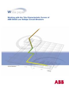
1 11 Analog Applications JournalUnderstanding output voltage limitations ofDC/DC buck convertersIntroductionProduct datasheets for DC/DC converters typically showan operating range for input and output voltages. Theseoperating ranges may be broad and in some cases mayoverlap. It is usually not possible to derive any arbitraryoutput voltage from the entire range of permissible inputvoltages. There are several factors that can cause this,including the internal reference voltage , the minimumcontrollable ON time, and the maximum buck-converter operationConsider the theoretical, ideal buck converter shown inFigure 1. The buck converter is used to generate a loweroutput voltage from a higher DC input Instruments IncorporatedPower ManagementBy John TuckerLow Power DC/DC Applications2Q Analog ProductsR2R1 LOUTCOUTS1S2 ErrorAmplifierPWMC omparatorVREFVINVOUTF eedbackVoltage+RampGeneratorControl LogicandGate Drive+ + Figure 1.
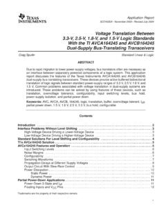
2 Theoretical, ideal buck converterIf the losses in the switch and catch diode are ignored,then the duty cycle, or the ratio of ON time to the totalperiod, of the converter can be expressed as(1)The duty cycle is determined by the output of the erroramplifier and the PWM ramp voltage as shown in Figure ON time starts on the falling edge of the PWM rampvoltage and stops when the ramp voltage equals the out-put voltage of the error amplifier. The output of the erroramplifier in turn is set so that the feedback portion of theoutput voltage is equal to the internal reference closed-loop feedback system causes the output volt-age to regulate at the desired level.
3 If the output of theDVVOUTIN=.Error AmplifierOutputDuty Cycle0%100%50%PWM RampFigure 2. Typical PWM waveforms at duty-cycle extremes and midpointTexas Instruments IncorporatedPower Management12 Analog Applications JournalHigh-Performance Analog 2008error amplifier falls below the PWM ramp minimum, thena 0% duty cycle is commanded, the converter will notswitch, and the output voltage is 0 V. If the error-amplifieroutput is above the PWM ramp peak, then the command-ed duty cycle is 100% and the output voltage is equal tothe input voltage . For error-amplifier outputs betweenthese two extremes, the output voltage will regulate to(2)Practical limitationsFor the ideal buck converter, any output voltage from 0 Vto VINmay be obtained.
4 In actual DC/DC converter circuits,there are practical limitations . It has been shown that theoutput voltage is proportional to the duty cycle and inputvoltage. Given a particular input voltage , there are limita-tions that prevent the duty cycle from covering the entirerange from 0 to 100%. Most obvious is the internal refer-ence voltage , VREF. Normally, a resistor divider network asshown in Figure 1 is used to feed back a portion of theoutput voltage to the inverting terminal of the error ampli-fier. This voltage is compared to VREF; and, during steady-state regulation, the error-amplifier output will not gobelow the voltage required to maintain the feedback volt-age equal to VREF.
5 So the output voltage will be(3)As R2 approaches infinity, the output voltage goes toVREFso that the output cannot be regulated to below thereference may also be constraints on the minimum control-lable ON time. This may be caused by limitations in thegate-drive circuitry or by intentional delays. This minimumcontrollable ON time puts an additional constraint on theminimum achievable VOUT:(4)where ton(min)is the minimum controllable ON time and fsis the switching duty cycle may also be constrained at the upperend. In many converters, a dead time is required to chargethe high-side switching FET gate-drive circuit. Feedforwardcircuitry may also cause a flattening of the PWM rampwaveform as the slope of the PWM ramp is increased whilethe period remains constant.
6 This will limit the maximumoutput voltage with respect to VIN. Typically, if there is amaximum duty-cycle limit, it will be expressed as a per-centage, and the maximum output voltage will be(5)Effect of circuit lossesSo far we have assumed that the components in the circuitare ideal and lossless. Of course, this is not the are conduction losses associated with the compo-nents that are important in determining the minimum andVVDOUTIN(max) VtVfOUTonINs(min)(min),= VVRROUTREF=+ .maximum achievable output voltage . Most important ofthese are the on resistance of the high- and low-sideswitch elements, and the series resistance of the outputinductor.
7 Taking these losses into account, we can nowexpress the duty cycle of the converter as(6)where rDS1is the on resistance of the high-side switch, S1;rDS2is the on resistance of the low-side switch, S2; and RLis the output -inductor series resistance. Since the lossterms are added to the numerator and subtracted fromthe denominator, the duty cycle increases with increasingload current relative to the ideal duty cycle. This has theeffect of increasing the available minimum voltage . Theworst-case situation for determining the minimum avail-able output voltage occurs when the input voltage is at itsmaximum specification, the output current is at the mini-mum load specification, and the switching frequency is atits maximum value.
8 The minimum output voltage is then(7)In contrast, the loss terms decrease the available maxi-mum voltage , and the worst-case conditions occur at theminimum input voltage and maximum load current. Sincethe limiting factor, maximum duty cycle, is specified as apercentage, the switching frequency is not relevant. Themaximum available output voltage is given by(8)ExamplesNow we can consider a typical application and calculatethe minimum and maximum output voltages. For thisexample, the input- voltage range is 20 to 28 V, and theload current required is 2 to 3 A. Table 1 shows typicaldatasheet characteristics of the DC/DC we need to calculate the minimum available outputvoltage by substituting the following parameters intoVDVI rrIOUTINOUTDSDSOUT(max)max(min)(max)(max )[()][= 12 +()].
9 RRDSL2 VtfVIrrOUTonsINOUTDSDS(min)(min)(max)(ma x)(min)[()= 12]][()].(min) +IrROUTDSL2 DVI rRVIr rOUTOUTDSLINOUTDSDS=+ + ()(),212 PPAARRAAMMEETTEERRMMIINNIIMMUUMMNNOOMMII NNAALLMMAAXXIIMMUUMMR eference voltage (V) Frequency (kHz)400500600 Minimum Controllable ON Time (ns)--150200 Maximum Duty Cycle (%)87----FET rDS(on)(VIN< 10 V) (m )--150--FET rDS(on)(VIN= 10 to 30 V) (m )--100200 Table 1. Typical datasheet characteristics of DC/DC converterTexas Instruments IncorporatedPower Management13 Analog Applications Journal2Q Analog ProductsEquation 7: ton(min)= 200 ns, fs(max)= 600 kHz, rDS1= rDS2= rDS(on)= 100 m , VIN(max)= 28 V, and IOUT(min)= 2 the worst-case conditions occur when ton(min)and fsare at the maximum and the loss terms are at a minimum,we use the appropriate specifications from Table 1.
10 We alsoneed to supply the series resistance of the output typical value for the series resistance is 25 m , soEquation 7 can be solved asTo calculate the maximum output voltage , we need tosubstitute the following values into Equation 8: rDS1= rDS2= rDS(on)(max)= 200 mW, VIN(min)= 20 V, IOUT(max)= 3 A,Dmax= 87%, and RL= 25 mW. With these values,Equation 8 becomesIn the example, both switch elements, S1 and S2, areconsidered active switches. This configuration is the syn-chronous buck regulator. If both switches are internal tothe converter s integrated circuit, they will likely have thesame on-resistance characteristics, and IOUT (rDS1 rDS2)will be zero.