Transcription of Understanding Quartz Crystals - Mtronpti.com
1 MtronPTI reserves the right to make changes to the product(s) and service(s) described herein without notice. No liability is assumed as a result of their use or see for our complete offering and detailed datasheets. Contact us for your application specific requirements: MtronPTI usage and applications for Quartz crystal devices is increas-ing with each new technological advancement in computers andperipherals, consumer electronics, telecommunications, and in-dustrial electronics. More and more engineers are now respon-sible for specifying crystal parameters for their specific applica-tion. Along with this new responsibility comes the need to betterunderstand crystal devices. This Engineering Note will attemptto take away some of the mystery in trying to define certain pa-rameters for Quartz and Its PropertiesThe Quartz crystal or resonator operates due to the piezoelectriceffect. The piezoelectric effect of Quartz allows it to produce anelectrical charge on its surface when the same surface(s) aredistorted or subjected to pressure.
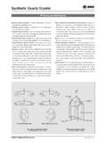
2 This distortion allows the crys-tal to vibrate at a particular resonant frequency. Conversely, theapplication of an alternating voltage produces the same type ofmechanical is one of several forms of silicon dioxide (SiO2) that isfound in nature; mostly in Brazil. Natural Quartz is costly to , most of the Quartz used for crystal fabrication to-day is of the cultured or synthetic variety. Cultured Quartz isproduced by placing small seeds of Quartz mixed with an alka-line solution in an autoclave. This mixture is subjected to highheat (> 400 C) and high pressure (30,000 psi). This causes thequartz to dissolve and reform as thin slices of Quartz . This pro-cess takes approximately 30-45 is ideal for use as a frequency determining device be-cause of its predictable thermal, mechanical, and electrical char-acteristics. The Quartz crystal is one of the few devices that canprovide a high-Q (quality factor) that is needed for precise fre-quency control in oscillators used as a timing Vibrational Modes and Orientation AngleThere are many different vibrational modes for Crystals as shownin Figure 1.
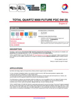
3 The frequency versus temperature characteristicsof Quartz crystal are primarily determined by the orientation angleat which the Quartz wafers are cut from a given bar of properties are dependent on the reference directionswithin the Crystals . These directions are referred to as axes .There are three axes in Quartz , the X, the Y and the Z. An idealcrystal would consist of a hexagonal prism with six facets ateach end. See Figure 2. A cross section taken from that prismwould look like the depiction in Figure Z-axis is known as the optical axis and repeats its physi-cal properties every 120 as the crystal is rotated about the Z-axis. The X-axis is parallel to a line bisecting the angles be-tween adjacent prism axis is called the electrical axis. Electrical polariza-tion occurs in this direction when mechanical pressure isapplied. An XT-cut crystal is produced from a slab of quartzcut from that portion of the Quartz bar that is perpendicu-lar to the X-axis.
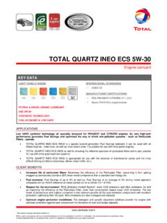
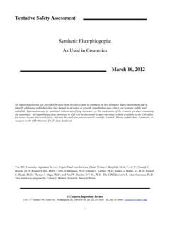
4 The XT-cut crystal if often referred to asa tuning fork crystal and is used extensively for Crystals such as the M-tron MMCC-1, MMCC-2, andSX1555. The frequency vs. temperature for the XT-cutcrystal is shown in Figure 3(Page 143).Figure 2 Figure 1 Understanding Quartz CrystalsMtronPTI reserves the right to make changes to the product(s) and service(s) described herein without notice. No liability is assumed as a result of their use or see for our complete offering and detailed datasheets. Contact us for your application specific requirements: MtronPTI Y-axis, which is also known as the mechanical axis ,runs at right angles through the face of the prism, and atright angles to the X-axis. Most Y-axis Crystals vibrate intheir sheer modes ; face shear for low frequency CT andDT cut Crystals , and the thickness shear for higher fre-quency AT and BT cut AT cut is the most popular of the Y-axis group be-cause of its excellent frequency vs.
5 Temperature charac-teristics. The AT cut is produced by cutting the Quartz barat an angle of approximately 35 15 from the Z-axis. Fig-ure 4 shows the frequency vs. temperature characteris-tics for AT-cut crystal has electrodes deposited on both sides. These elec-trodes are made of a low resistance metal such as silver, goldand aluminum. The electrode structure allows for an electricalvoltage to be applied to the crystal in order to produce mechani-cal vibration. The electrode also provides a means of attachingthe crystal to the mounting structure of the crystal base. Seefigure 5. Because the frequency of the crystal is related to its thickness,there is a limitation in the manufacturing of high frequency fun-damental Crystals . The higher the frequency, the thinner the crys-tal in manufacturing for these high frequency Crystals usu-ally stem from breakage during lapping and mounting. Theselosses result in lower yields and consequently a higher frequencies up to 35 MHz are attainable usingstandard crystal designs and processes.
6 For frequencies above35 MHz overtone modes or fundamental inverted mesa crys-tals are recommended. With overtone modes only odd numberharmonics or multiples can be generated. Fundamental invertedmesa designs up to 500 MHz are overtone modes are 3rd, 5th, 7th, and 9th. The actualfrequency of oscillation of an overtone crystal is not an exactmultiple of the crystal fundamental. As an example, a 60 MHz3rd overtone crystal would physically look like a 20 MHz main difference being that certain electrical parameters areoptimized in order to provide frequency of oscillation to occur at60 Mhz when used in an overtone oscillator will also exhibit unwanted or spurious modes whenoscillating at the design frequency. These unwanted modes areinfluenced by the crystal surface finish, diameter and thicknessdimensions, and mounting technique. These spurious modesare expressed in terms of equivalent series resistance refer-enced to the design mode of the crystal , or in terms of energylevel in dB referenced to the carrier a crystal is designed for optimum energy and perfor-mance at the desired operating frequency with spurious energylevels being suppressed to some degree.
7 If spurious modesare of concern to the designer, every effort should be made toconsult with the crystal manufacturer before finalizing the crystal resonator is usually a round disc. The thick-ness (d) of the disc is related to the fundamental modefrequency (f) by the equation:Figure 5 Figure 3 Figure 4 Understanding Quartz Crystalsf (kHz) =Nd(mm)Where N = 1660 kHz x mmMtronPTI reserves the right to make changes to the product(s) and service(s) described herein without notice. No liability is assumed as a result of their use or see for our complete offering and detailed datasheets. Contact us for your application specific requirements: MtronPTI crystal Equivalent Circuit, Motional Parameters, andQuality FactorThe Quartz crystal can be represented electrically by the circuitshown in figure 6. The motional inductance (Lm), motional ca-pacitance (Cm), and series resistance ( R ) form a series reso-nant CIR order of 4 to 7 pF.
8 All these motional parameters canbe measured using a crystal impedance (CI) the actual values for these motional parameters are afunction of the design frequency. In applications requiring con-trol of spurious responses or where the crystal needs to be pulled in frequency, the designer may need to specify the de-sired motional parameters. The series resonant frequency (Hz)of the crystal is represented by the formula:Where Lm is in Henries and Cm in Q of a crystal is the quality factor of the motional param-eters at resonance. The maximum stability of a crystal is directlyrelated to the Q of the crystal . The higher the Q the smallerthe bandwidth and the steeper the reactance curve. See figure6. The Q can be expressed as:V. crystal LoadingThe loading of the crystal is critical in order to have a prop-erly functioning oscillator. Figure 8 shows a typical Pierceoscillator comprised of an HCMOS inverter being used asan active linear circuit is commonly used with fundamental mode crys-tals.
9 The inverter is biased into a linear mode by feedbackresistor RF. Depending on the frequency of operation, thisfeedback resistor will usually have a value in the 500K to2 Meg ohm range. Resistor R1 can be used to control thedrive to the crystal and will typically have a value that isabout equal to the reactance value of capacitor C2. Val-ues will range between 200 to 2700 ohms some applications this resistor may not be needed. Care-ful selection of capacitors C1 and C2 will insure optimumstartup and loading conditions for the crystal . The capaci-tor values are critical because the oscillator circuit relieson wideband noise in order to get the oscillator to the inverter stage will provide a 180 phase shiftbetween its input and output. The crystal and the two ca-pacitors provide additional 180 phase allowing for in-phase energy to be applied to the input of the inverterstage.
10 This completes the feedback loop and oscillationcan occur as long as the inverter can provide a voltagegain that is greater than 1. Because the crystal in this ex-IV. Series and Parallel ResonanceWhen a crystal is operating at series resonance (fs), seefigure 7, it appears resistive in the oscillator circuit. The im-pedance of the crystal is near zero at resonance. No loadcapacitance needs to be specified for Crystals intended foruse in a series resonant oscillator circuit. Most higher over-tone (5th, 7th, and 9th) Crystals will be specified as seriesresonant a crystal is operating at parallel or anti resonance(fa), see Figure 7, it appears inductive in the oscillator cir-cuit. The crystal s impedance is highest at this anti-reso-nance point. Under this condition the crystal is sensitive tochanges in circuit reactance values. For Crystals operatingin a parallel resonant oscillator the load capacity of the crys-tal should always be specified in order to insure proper fre-quency control and 7 Figure 8 Figure 6Fs =12 Lm CmQ ==12 Fs R Cm2 Fs LmRUnderstanding Quartz CrystalsMtronPTI reserves the right to make changes to the product(s) and service(s) described herein without notice.