Transcription of Understanding the fundamentals of CPU architecture
1 TVE-E 18 009 Examensarbete 15 hpJuni 2018 Understanding the fundamentals of CPU architecture Bachelor project in Electrical engineering Christian alkzairAltin JanuziAndreas Blom Teknisk- naturvetenskaplig fakultet UTH-enheten Bes ksadress: ngstr mlaboratoriet L gerhyddsv gen 1 Hus 4, Plan 0 Postadress: Box 536 751 21 Uppsala Telefon: 018 471 30 03 Telefax: 018 471 30 00 Hemsida: AbstractUnderstanding the fundamentals of CPU architectureChristian Alkzair, Altin Januzi, Andreas BlomUnderstanding how a computer or rather a CPU works can be a bit tricky and hard to understand. We live today in a society full of computers and there are many who do not understand how a CPU works. This project is aimed to understand how a CPU works and the architecture behind it. For this it is demonstrated the fundamental theory behind it but also a practical computer that has been built from scratch. This computer can demonstrate the theory behind how the CPU works and also how it communicates.
2 This computer is 8-bit which has it limitations but can show the fundamental theory behind how computers work. ISSN: 1654-7616, TVE-E 18 009 Examinator: Hana Barankova mnesgranskare: Ladislav BardosHandledare: Stefanos Kaxiras Contents 1. Nomenclature3 2. Introduction4 Background4 Goal4 Limitations4 3. Theory5 Clock module5 Registers6 ALU6 Output7 Counter7 RAM7 Bus9 4. Experimental Details10 Designing the computer10 Building the computer10 Clock module11 Registers11 Output12 Counter13 RAM13 BUS14 Programming microcode16 Running the code on the computer17 5. Results18 6. Discussion19 Design of the computer19 Troubleshooting19 7. Conclusion21 8. Reference list22 1. Nomenclature CPU - Central Processing Unit TTL - Transistor-transistor logic, a type of integrated chip build with bipolar transistors CMOS - Complementary metal-oxide-semiconductor, a type of integrated chip built with mosfets.
3 I/O - Input/Output, lines/pins on chips which output or reads data when bits has been applied. EEPROM - electrically erasable programmable read-only memory ALU - Arithmetic logic unit, digital circuit which can input two binary numbers and either add or subtract. BUS - A BUS is used for communications with all different modules in the architecture of a computer. 1 2. Introduction Background Understanding the complexity of how computers works can be hard today. Society and computers has advanced in the recent decades a lot in the digital circuits and processors that many people don't even realise what is happening when they are sitting in front of their phones or computers. The era of transistors and computers has been strongly growing with each year and with each year passing by there is more people who do not understand this technology. Goal The goal of this project is to show the theory behind how a simple computer work.
4 For that all the necessary theory will be gone through. On top of that a 8 bit computer will be built which will show how the theory works and how that will respond in the practical case. Limitations The limitations of this project is time and practicality, since the complexity of the computer rises exponentially with each new feature and the more practicality the computer has. Building the computer takes time and by building it with TTL chips the size and cost can be very high, as well as the potential of faults which manifests as time for troubleshooting which has therefore been the fundamental limitation on this project. 2 3. Theory To fully understand how a computer work it is needed to understand first the components of which it is built of. A processor will have Clock module Registers ALU Output Counter RAM Bus Clock module The clocks function in the computer is to cycle forward the data or instructions.
5 The clock is a crucial component and without the clock module the computer will simply not work or rather not show any progress of the data. The clock module also determines how fast the computer can execute instructions. This is most commonly measured in frequency (Hz), and is the CPUs main engine on how fast it can execute the instructions. The clocks output will be voltages driven outputted in pulses. These pulses will enter all the modules of the computer, this will make the computer work with after the clock outputs a pulse. For the simple case there is digital circuit such as the 555 Timer IC. This clock can be regulated with only a capacitor and a resistor, the values of the chosen components will determinate on how fast the clock will cycle. 1 A clock can also be driven differently by outputting either in mono, astable and bistable mode. In the astable mode the clock will push out pulses without any condition. This means that when the clock is in astable mode the computer will run continuously.
6 More or less the clock will be driven as a oscillator in the astable mode. 1 555 timer tutorial , , retrived 17 may 2018. 3 For the monostable mode the clock will only output when a certain command or input has been applied. This can be in the most easiest way be in a push button which will output a voltage when the pushbutton is pressed. The bistable mode works in a way that the clock module will be on when input has been applied. This way the clock will work as a basic flip flop and will be always on until the circuit or the clock has been reset. Combining with OR and AND gates it is possible to cycle between the different modes with the 555 timer. Registers Registers are the processors component which hold values (voltages). These registers contain small amount of fast memory which hold values stored into them. This will make registers unique in away that they will be part of the important instructions. Instructions such as mathematical numbers (written in bits) can be stored in registers and then move these numbers where they should belong.
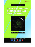
7 In a common computer there are lots of registers, these registers can have different functions of what they store but most commonly they store values which are intended to be input in other modules which will do mathematical operations. ALU The ALU or Arithmetic logic unit is the computer s mathematical processor. The ALU can input bits from different registers and then do mathematical operations when the registers values are input. 4 Source: Looking at the picture above the ALU inputs usually two integers from the registers (A and B) and then proceeded to do its operation and then output it. Limitations of the ALU is only how big the bits of numbers are. For example on an 8-bit ALU, the ALU can only output a maximum of 256, meaning that if the ALU gets two values which both are 256 will lead to it only outputting 256. Since the ALU can do mathematical operations the most common instruction it can do is either add or subtract values, meaning that it can either do add register A value with register B or subtract value B with A vice verse.
8 More complex ALUs can do more complex operations such as square root of values. 2 Output The output module of the computer consist of a register which holds a value intended for output. In most cases the output also consist of some graphical component which can show what kind of value the output register holds. Most commonly the output register is only used for the computers final instructions or result and its intents is only to show what the computer has calculated. Counter Using a counter or rather a program counter is crucial. The counter tells in most cases on what the computer should begin with. It can also be used as a indicator on what stage the computer is at. This way it is possible to use the counter as a indicator of exactly what stage the computer is at, and also feed this information along for longer program chains. RAM The RAM or Random Access Memory is the computer's main storage of programs. There is two kinds of memory, static and dynamic RAM.
9 Static RAM uses flip-flops to store the data while dynamic stores the data in a capacitor combined with other digital circuit. This will 2 Jerald A Brown. Albert P Malvino, digital computer electronic , nr 3, 1999, p 79-90. 5 make the static memory lose its data when it loses power while the dynamic memory can still hold data. 3 For simple projects static RAM is usually used since its faster, easier and more reliable than dynamic memory but can store less values and costs more. Static RAM stores data in its I/O and this data can be accessed or output when the RAM receives data (integer) in its address lines. The address lines is in a sense the rams locator of where the data is being stored. This will make the RAM versatile that it can store values up depending on how big the address is. But the memory has also limitations that it cannot store bits bigger than what it is designed for. Ram chips have both read and write functions.
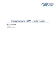
10 When in write mode the RAM will store the data in the I/O pins to the selected address line while in read function the RAM will output the data in the I/O lines from the selected address lines. Source: In this picture the inputs which are shown are the address, CS (Chip enable), OE (Output enable) and WE (Write enable). Assuming an easy example of 2 bit RAM, when applying voltage for example to the write enable pin will make the data from the I/O stored in the selected bit of the address, likewise is on the output enable which will read the the selected address data and output it in the I/O. The chip enable pin will activate the ram for usage. This way the enable pin can assure lower power consumption when the data in the ram is not used. 3 Sergei Skorobogatov (June 2002). "Low temperature data remanence in static RAM". University of Cambridge, Computer Laboratory. Retrieved 17 may 2018. 6 By having two different modes of the chip (WE and OE) there has to be some kind of external input such as switch buttons and data enabling pins.