Transcription of Understanding the Pulsation & Vibration Control …
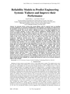
1 Presented at the 2004 Gas Machinery Conference in Albuquerque, New Mexico. October 4-7, 2004 Understanding the Pulsation & Vibration Control Concepts in the New API 618 Fifth Edition Kenneth E. Atkins Engineering Dynamics Incorporated Alan S. Pyle Shell Global Solutions (US) Inc. James D. Tison Engineering Dynamics Incorporated The Fifth Edition of API Standard 618 for reciprocating compressors will be published in the near future. This short course explains the changes from the previous editions and discusses the acoustical design philosophy required to achieve safe and reliable piping systems for reciprocating compressors. i Presented at the 2004 Gas Machinery Conference in Albuquerque, New Mexico. October 4-7, 2004 TABLE OF CONTENTS 1. INTRODUCTION .. 1 2. BASICS OF EXCITATION MECHANISMS IN RECIPROCATING COMPRESSORS .. 2 Pulsation EXCITATION MECHANICAL EXCITATION 3.
2 UNDERSTAND LIMITATIONS OF MECHANICAL 4 INACCURACY OF MECHANICAL NATURAL FREQUENCY EFFECT OF INACCURACIES OF MECHANICAL NATURAL INACCURACIES OF FORCED RESPONSE 4. Pulsation AND SHAKING FORCE Control USING REACTIVE ACOUSTICAL 7 DESIGN USING ACOUSTIC FILTERING IN CONJUNCTION WITH GOOD MECHANICAL SUPPORT COMPARISON OF Pulsation Control MECHANICAL ANALOGIES AND INTERPRETATION OF SURGE VOLUMES AND Surge Volumes .. 10 Filters .. 10 Design Procedure for Heavy Gases Using Reactive Pulsation Control (Acoustic Velocity < 2000 ft/s) .. 10 5. CHANGES FOR API 618 FIFTH 11 RESIDUAL NON-RESONANT FORCE 6. CASE HISTORIES .. 16 FAILURE OF 10 SUCTION FAILURE OF SUCTION BOTTLE GAS TRANSMISSION STATION PIPING TYPICAL PACKAGED HIGH SPEED 7. 21 1 Presented at the 2004 Gas Machinery Conference in Albuquerque, New Mexico. October 4-7, 2004 Abstract The Fifth Edition of the API 618 specification is scheduled to be published in early 2005.
3 Significant changes have been incorporated into the section concerning Pulsation and Vibration Control . Specific guidelines are included to explain the necessity to perform certain analyses (that were optional in the Fourth Edition) based on pressure Pulsation and shaking force levels determined from the acoustical simulation. This will hopefully reduce the ambiguity in determining whether or not forced mechanical response calculations should be performed. The purpose of this short course is to provide the user with a working knowledge of good engineering practices for Pulsation and Vibration Control for reciprocating machinery commonly used in the natural gas industry. An in-depth explanation of the changes in API 618 and the differing design philosophies will be presented.
4 Several example cases illustrating design concepts will be used. 1. Introduction In the 1950 s and 60 s, design techniques using analog simulation tools for the Control of Pulsation in compressor piping systems were developed. Acoustical designs utilizing reactive Pulsation Control (acoustic filtering), in combination with resistive elements (orifice plates) where necessary, became very successful in controlling Pulsation levels transmitted to piping, piping shaking force, and bottle unbalanced force. Over the last 20 years, digital techniques have progressed significantly as the speed and capacity of computers have developed. Today, digital techniques for acoustic simulation are in greater overall use worldwide than analog methods. However, in recent years there has also been a trend in some industry segments away from utilization of effective Pulsation Control techniques and toward more reliance on mechanical techniques to Control Vibration .
5 There are several reasons for this trend. First, the basics of Pulsation Control theory are not trivial and capabilities vary significantly among users of available software. Reactive Pulsation Control (acoustic filtering) requires more design effort. Generally, single surge volume designs in conjunction with resistive elements (orifice plates) require significantly less engineering effort and technical expertise. Another reason for this trend is the proliferation of finite-element based structural dynamics software for piping. Most pipe stress analysis package on the market today claim some dynamic analysis capabilities. Mechanical natural frequencies and forced Vibration levels of complex piping systems, once modeled, can be calculated fairly easily. However, the lack of Understanding of the limitations on the accuracy of these calculations can lead to serious problems and in some cases disastrous consequences.
6 As will be shown herein, even if the structural dynamics calculations were extremely accurate, there is no justification for the risk involved by designing systems with inadequate Pulsation Control . The Fifth Edition of the API 618 specification will continue to include language concerning mechanical natural frequency and forced response calculations. While such calculations can be performed to any degree of accuracy in theory, practical considerations put limits on the accuracy that is actually achievable. It is the goal of this tutorial to illustrate this point, and to present well-established design techniques that can reduce the dependence on expensive (and often problematic) mechanical natural frequency and forced response analyses for the qualification of piping system designs.
7 2 Presented at the 2004 Gas Machinery Conference in Albuquerque, New Mexico. October 4-7, 2004 QsHeadEndQdCrank End QsHeadEndQdCrank End Actual Piston MotionCrank Angle (Degrees)Piston VelocitySine Wave10020030036000maxVminVActual Piston MotionCrank Angle (Degrees)Piston VelocitySine Wave10020030036000maxVminVActual Piston MotionCrank Angle (Degrees)Piston VelocitySine WaveSine Wave10020030036010020030036000maxVminV10 0-400-2000200400 Degrees of RotationFlow Amplitude2003004000 Flow vs. Time100-400-2000200400 Degrees of RotationFlow Amplitude2003004000 Flow vs. Time2. Basics of Excitation Mechanisms in Reciprocating Compressors Pulsation Excitation Mechanisms Reciprocating compressors generate flow modulations which in turn generate pressure Pulsation . The flow modulations come about as a result of intermittent flow through the suction and discharge valves, with some geometry effects due to the (finite) length of the connecting rod.
8 Figure 1. Reciprocating Compressor Slider Crank Mechanism Figure 1 shows a schematic of a compressor cylinder. The suction flow (QS) enters the cylinder, and the discharge flow (QD) exits the cylinder. The velocity of the piston, shown in Figure 2, is approximately sinusoidal in shape. The deviation of the actual piston motion from the sinusoidal shape is due to the finite length of the connecting rod. As the ratio of the connecting rod length to the crank radius (L/R) is increased, the shape becomes more closely sinusoidal. The pressure Pulsation generated by the compressor is proportional to the flow (QS or QD) modulation. Since the flow is based on the product of the piston velocity and the piston swept area, the shape of the discharge flow at the piston face is of the same shape as the piston velocity curve (Q = Area Velocity).
9 Since the suction and discharge valves of each cylinder end ( , the head end) of a compressor are never open simultaneously, the suction and discharge piping systems are isolated acoustically. Therefore, the flow excitation of either the suction or discharge can be considered independently for the purpose of Understanding the Pulsation excitation mechanism. Figure 2. Piston Velocity for Slider Crank Mechanism Figure 3. Single Acting Compressor Cylinder (L/R = , Ideal Valves) Figures 3-6 show the effect of the valve action on flow through the discharge valves of a compressor. Figure 3 shows the discharge valve flow versus time for a single-acting 3 Presented at the 2004 Gas Machinery Conference in Albuquerque, New Mexico. October 4-7, 2004 100-400-2000200400 Degrees of RotationFlow Amplitude2003004000 Flow vs.
10 Of RotationFlow Amplitude2003004000 Flow vs. During compression, the suction and discharge valves are closed. When the pressure in the cylinder reaches the discharge back pressure, the discharge valve opens, and the flow versus time wave through the valve has the shape of a portion of the piston velocity curve shown in Figure 2. As the cylinder reaches TDC, the discharge valves close, and the flow returns to zero. 1 2 3 4 5 6 7 8 9 101112131415161718192000255075100125 HarmonicFlow Amplitude1 2 3 4 5 6 7 8 9 10111213141516171819200 1 2 3 4 5 6 7 8 9 10 11 12 13 14 15 16 17 18 19 20002550751001250255075100125 HarmonicFlow Amplitude Figure 4. Flow Frequency Spectrum for Single Acting Cylinder A frequency analysis of the flow wave of Figure 3 is shown in Figure 4.