Transcription of Unit 24: Applications of Pneumatics and Hydraulics
1 1 Unit 24: Applications of Pneumatics and Hydraulics Unit code: J/601/1496 QCF level: 4 Credit value: 15 OUTCOME 2 TUTORIAL 4 directional CONTROL valves The material needed for outcome 2 is very extensive so there are ten tutorials in this outcome. You will also be completing the requirements for outcome 1 which is integrated into it. The series of tutorials provides an extensive overview of fluid power for students at all levels seeking a good knowledge of fluid power equipment. 2 Understand the construction, function and operation of pneumatic and hydraulic components, equipment and plant pneumatic equipment: types, construction, function and operation air compressors, coolers, dryers, receivers, distribution equipment, fluid plumbing and fittings, drain traps, FRL air service units, valves , actuators, seals hydraulic equipment: types, construction, function and operation fluids, pumps, motors, actuators, reservoirs, accumulators, fluid plumbing and fittings, valves , filters, seals, gauges Performance characteristics: air compressors volumetric efficiency, compression ratio, isothermal efficiency.
2 hydraulic pumps operating efficiency, losses, flow rate, operating pressure, shaft speed, torque and power On completion of this tutorial you should be able to do the following. Explain the principles and symbols of directional control valves . Explain the different port configurations of directional control valves . Explain the different ways valves are moved. Describe the construction of different types of directional valves . Explain the importance of standard valve bases and manifolds. 2 directional valves 1. INTRODUCTION valves are necessary to control the pressure, flow rate and direction of the fluid. hydraulic valves are made to a high standard of quality and robustness.
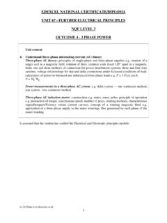
3 The diagram shows a few of the vast range of hydraulic valves available. We should remember always that hydraulic systems are high pressure systems and pneumatic systems are low pressure systems. hydraulic valves are made of strong materials ( steel) and are precision manufactured. pneumatic valves are made from cheaper materials ( aluminium and polymer) and are cheaper to manufacture. Figure 1 We will start by considering how the fluid is directed from the pump/compressor to the actuator and back to the tank/atmosphere. Consider the basic circuit below. Figure 2 The directional control valve must direct the flow from the pump either to port A or port B.
4 The oil being exhausted by the cylinder must be directed from the other port back to tank. The number of ports (external connections) and the number of positions describe such valves . The valve shown has 5 ports and 3 positions so it is designated as a 5/3 directional control valve. 3 The basic symbol for a valve is a rectangle to which external connections are drawn. Inside the rectangle, the internal connections are shown for the normal position of the valve. Extra boxes show the internal connections for the other positions of the valve. Figure 3 shows a 4/2 valve and matching symbol to BS2917. In Hydraulics the pressure port is designated P and the return port R or T (for tank).
5 The two other ports are designated A and B. In Pneumatics the pressure port is numbered (1) and the exhaust port (3). The other two are numbered (2) and (4). Note how in the normal position P connects to B and A to T. In the operated position P is connected to A and B to T thus reversing the flow directions at A and B. Figures 3 The left box of the symbol shows the connections for the normal position. The right box shows the connections when the spool is moved to the left. The identification tags A, B, P and T are placed against the normal position of the valve. Note this particular valve has a push button to operate it and a spring to return it to the normal position.
6 This is also shown on the symbol. If the valve has a neutral position such that nothing is supplied to neither A nor B, then a third rectangle is inserted in the middle of the symbol ( ). The valve is then a 4/3 valve. There are various ways the ports may be connected in the middle position for various reasons. In they are all shown blocked off. Figure 4 4 When the P connection is blocked off the valve is said to have a closed centre. A slight modification as shown in figure 5 allows all the ports to be joined in the centre position. When P is connected to T in the middle position, it has an open centre. This allows the pump to vent to tank in the neutral position so saving energy and wear and tear on the pump.
7 The disadvantage of an open centre is that you lose the system pressure so nothing else can be used from with pump. Figure 5 Besides showing the internal connections, a valve symbol must show how the valve element is moved. This is done by adding a small box at each end containing the symbol showing how it is done. Some examples are shown below. A Hand lever operated and pilot return. B Pilot operated and pilot return. C Push knob operated and spring return. D 3 position valve pilot/pilot with spring centring. E Solenoid operated and solenoid return. F Roller operated and spring return. Figure 6 5 2. VALVE BASES directional and other valves are usually designed to be mounted on a separate base.
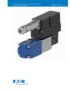
8 The external pipe work is connected to the base. The advantage of this is standardisation of designs and it allows the valve to be removed without disconnecting the pipe work. hydraulic bases to ISO size 6 and 10 are shown below. Figure 7 Machines used in industrial Applications use several valves and it is convenient to mount them on a manifold so that supply and exhaust connections are common to all. This is a common design for air valves . Figure 8 6 3. OTHER DESIGNS. POPPET valves The directional control valves so far studied are all of the type that uses a sliding piston or spool. Other designs use flat plates and poppets but the functions are the same although they may not be as robust and are more suited to Pneumatics .
9 Poppets make take the form of a ball, a flat plate or a cone. The diagram shows a 3/2 poppet valve. In the position shown P is connected to A. When a force is applied the poppet moves to the other position and flow is from A to T. Figure 9 The diagram below shows a 5/2 poppet valve. This is more common for Pneumatics than Hydraulics . Figure 10 7 ROTARY valves The diagram shows a cross section through 4/3 valve. When the element is rotated about its axis, the passages A, B ,P and T are connected as shown. Figure 11 8 CARTRIDGE valves These are forms of poppet valve designed to fit into a manifold block. Just about all valve types can be designed as a cartridge to fit into a block specially machined to accept it.
10 In this way a bank of valves may be built into one block. The block might contain directional valves , relief valves , flow dividers, one way valves and so on. Figure 12 The directional valves are in the main pilot/solenoid operated. The next diagram shows a 2 way normally closed design. In the de-energised state, the pressure forces the poppet closed against the valve seat. When the solenoid is energised, the pilot poppet is lifted up venting the pressure on top of the main poppet so allowing it to be pushed upwards by the system pressure and opening the passage through the valve seat. Figure 13 9 4. METHODS OF OPERATING directional valves PILOT OPERATED valves The diagram below shows a pneumatic 3 port valve, pilot operated and spring returned.