Transcription of UNIT 3. INDUCTION MOTORS - Erode Sengunthar …
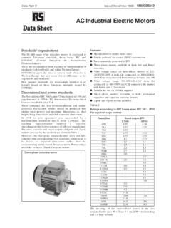
1 1 unit 3. INDUCTION MOTORS OBJECTIVE The aim of this chapter is to gather knowledge about the following topics of INDUCTION MOTORS . 1. Construction, types and principle of operation of 3-phase INDUCTION MOTORS . 2. Equivalent circuit of 3-phase INDUCTION motor . 3. The performance calculation by means of finding torque, slip and efficiency. 4. Different types of starters like auto-transformer starter, star-delta starter. 5. Various methods of speed control 3-phase INDUCTION motor . 6. Principle of operation of single phase INDUCTION motor . INTRODUCTION An INDUCTION motor (IM) is a type of asynchronous AC motor where power is supplied to the rotating device by means of electromagnetic INDUCTION .
2 The INDUCTION motor with a wrapped rotor was invented by Nikola Tesla Nikola Tesla in 1882 in France but the initial patent was issued in 1888 after Tesla had moved to the United States. In his scientific work, Tesla laid the foundations for understanding the way the motor operates. The INDUCTION motor with a cage was invented by Mikhail Dolivo-Dobrovolsky about a year later in Europe. Technological development in the field has improved to where a 100 hp ( kW) motor from 1976 takes the same volume as a hp ( kW) motor did in 1897. Currently, the most common INDUCTION motor is the cage rotor motor .
3 An electric motor converts electrical power to mechanical power in its rotor (rotating part). There are several ways to supply power to the rotor. In a DC motor this power is supplied to the armature directly from a DC source, while in an INDUCTION motor this power is induced in the rotating device. An INDUCTION motor is sometimes called a rotating transformer because the stator (stationary part) is essentially the primary side of the transformer and the rotor (rotating part) is the secondary side. INDUCTION MOTORS are widely used, especially polyphase INDUCTION MOTORS , which are frequently used in industrial drives.
4 INDUCTION MOTORS are now the preferred choice for industrial MOTORS due to their rugged construction, absence of brushes (which are required in most DC MOTORS ) and the ability to control the speed of the motor . 2 CONSTRUCTION A typical motor consists of two parts namely stator and rotor like other type of MOTORS . 1. An outside stationary stator having coils supplied with AC current to produce a rotating magnetic field, 2. An inside rotor attached to the output shaft that is given a torque by the rotating field. Figure. INDUCTION motor construction Figure.
5 INDUCTION motor components. Stator construction The stator of an INDUCTION motor is laminated iron core with slots similar to a stator of a synchronous machine. Coils are placed in the slots to form a three or single phase winding. 3 Figure. Single phase stator with windings. Figure. INDUCTION motor magnetic circuit showing stator and rotor slots Type of rotors Rotor is of two different types. 1. Squirrel cage rotor 2. Wound rotor Squirrel-Cage Rotor In the squirrel-cage rotor, the rotor winding consists of single copper or aluminium bars placed in the slots and short-circuited by end-rings on both sides of the rotor.
6 Most of single phase INDUCTION MOTORS have Squirrel-Cage rotor. One or 2 fans are attached to the shaft in the sides of rotor to cool the circuit. 4 Figure. Squirrel cage rotor Wound Rotor In the wound rotor, an insulated 3-phase winding similar to the stator winding wound for the same number of poles as stator, is placed in the rotor slots. The ends of the star-connected rotor winding are brought to three slip rings on the shaft so that a connection can be made to it for starting or speed control. It is usually for large 3 phase INDUCTION MOTORS .
7 Rotor has a winding the same as stator and the end of each phase is connected to a slip ring. Compared to squirrel cage rotors, wound rotor MOTORS are expensive and require maintenance of the slip rings and brushes, so it is not so common in industry applications. 5 Figure. Wound rotor of a large INDUCTION motor . (Courtesy Siemens). PRINCIPLE OF OPERATION An AC current is applied in the stator armature which generates a flux in the stator magnetic circuit. This flux induces an emf in the conducting bars of rotor as they are cut by the flux while the magnet is being moved (E = BVL (Faraday s Law)) A current flows in the rotor circuit due to the induced emf, which in term produces a force, (F = BIL) can be changed to the torque as the output.
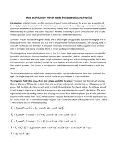
8 In a 3-phase INDUCTION motor , the three-phase currents ia, ib and ic, each of equal magnitude, but differing in phase by 120 . Each phase current produces a magnetic flux and there is physical 120 shift between each flux. The total flux in the machine is the sum of the three fluxes. The summation of the three ac fluxes results in a rotating flux, which turns with constant speed and has constant amplitude. Such a magnetic flux produced by balanced three phase currents flowing in thee-phase windings is called a rotating magnetic flux or rotating magnetic field (RMF).
9 RMF rotates with a constant speed (Synchronous Speed). Existence of a RFM is an essential condition for the operation of an INDUCTION motor . If stator is energized by an ac current, RMF is generated due to the applied current to the stator winding. This flux produces magnetic field and the field revolves in the air gap between stator and rotor. So, the magnetic field induces a voltage in the short-circuited bars of the rotor. This voltage drives current through the bars. The interaction of the rotating flux and the rotor current generates a force that drives the motor and a torque is developed consequently.
10 The torque is proportional with the flux density and the rotor 6 bar current (F=BLI). The motor speed is less than the synchronous speed. The direction of the rotation of the rotor is the same as the direction of the rotation of the revolving magnetic field in the air gap. However, for these currents to be induced, the speed of the physical rotor and the speed of the rotating magnetic field in the stator must be different, or else the magnetic field will not be moving relative to the rotor conductors and no currents will be induced.