Transcription of UNIT 3 POWER TRANSMISSION DEVICES Power ... - IGNOU
1 79 POWER TRANSMISSION DEVICES unit 3 POWER TRANSMISSION DEVICES Structure Introduction Objectives POWER TRANSMISSION DEVICES Belts Chain Gears TRANSMISSION Screw POWER TRANSMISSION by Belts Law of Belting Length of the belt Cone Pulleys Ratio of Tensions POWER Transmitted by belt Drive Tension due to Centrifugal Forces Initial Tension Maximum POWER Transmitted Kinematics of Chain Drive Classification of Gears Parallel Shafts Intersecting Shafts Skew Shafts Gear Terminology Gear Train Simple Gear Train Compound Gear Train POWER Transmitted by Simple Spur Gear Summary Key Words Answers to SAQs INTRODUCTION The POWER is transmitted from one shaft to the other by means of belts, chains and gears. The belts and ropes are flexible members which are used where distance between the two shafts is large. The chains also have flexibility but they are preferred for intermediate distances.
2 The gears are used when the shafts are very close with each other. This type of drive is also called positive drive because there is no slip. If the distance is slightly larger, chain drive can be used for making it a positive drive. Belts and ropes transmit POWER due to the friction between the belt or rope and the pulley. There is a possibility of slip and creep and that is why, this drive is not a positive drive. A gear train is a combination of gears which are used for transmitting motion from one shaft to another. 80 Theory of Machines Objectives After studying this unit , you should be able to understand POWER TRANSMISSION derives, understand law of belting, determine POWER transmitted by belt drive and gear, determine dimensions of belt for given POWER to be transmitted, understand kinematics of chain drive, determine gear ratio for different type of gear trains, classify gears, and understand gear terminology.
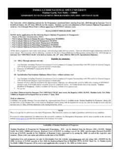
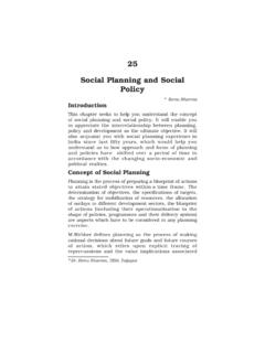
3 POWER TRANSMISSION DEVICES POWER TRANSMISSION DEVICES are very commonly used to transmit POWER from one shaft to another. Belts, chains and gears are used for this purpose. When the distance between the shafts is large, belts or ropes are used and for intermediate distance chains can be used. For belt drive distance can be maximum but this should not be more than ten metres for good results. Gear drive is used for short distances. Belts In case of belts, friction between the belt and pulley is used to transmit POWER . In practice, there is always some amount of slip between belt and pulleys, therefore, exact velocity ratio cannot be obtained. That is why, belt drive is not a positive drive. Therefore, the belt drive is used where exact velocity ratio is not required. The following types of belts shown in Figure are most commonly used : (a) Flat belt and Pulley (b) V- belt and Pulley (c) Circular belt or Rope Pulley Figure : Types of belt and Pulley The flat belt is rectangular in cross-section as shown in Figure (a).
4 The pulley for this belt is slightly crowned to prevent slip of the belt to one side. It utilises the friction between the flat surface of the belt and pulley. The V- belt is trapezoidal in section as shown in Figure (b). It utilizes the force of friction between the inclined sides of the belt and pulley. They are preferred when distance is comparative shorter. Several V-belts can also be used together if POWER transmitted is more. The circular belt or rope is circular in section as shown in Figure (c). Several ropes also can be used together to transmit more POWER . The belt drives are of the following types : (a) open belt drive, and (b) cross belt drive. Open belt Drive Open belt drive is used when sense of rotation of both the pulleys is same. It is desirable to keep the tight side of the belt on the lower side and slack side at the 81 POWER TRANSMISSION DEVICES top to increase the angle of contact on the pulleys.
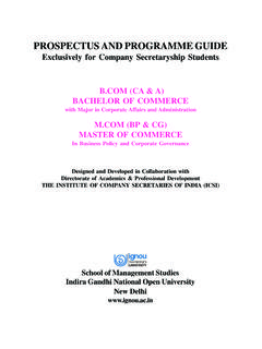
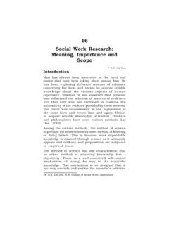
5 This type of drive is shown in Figure Figure : Open belt Derive Cross belt Drive In case of cross belt drive, the pulleys rotate in the opposite direction. The angle of contact of belt on both the pulleys is equal. This drive is shown in Figure As shown in the figure, the belt has to bend in two different planes. As a result of this, belt wears very fast and therefore, this type of drive is not preferred for POWER TRANSMISSION . This can be used for TRANSMISSION of speed at low POWER . Figure : Cross belt Drive Since POWER transmitted by a belt drive is due to the friction, belt drive is subjected to slip and creep. Let d1 and d2 be the diameters of driving and driven pulleys, respectively. N1 and N2 be the corresponding speeds of driving and driven pulleys, respectively. The velocity of the belt passing over the driver 11160dNV If there is no slip between the belt and pulley 221260dNVV or, 11226060d Nd N or, 1221 NdNd If thickness of the belt is t , and it is not negligible in comparison to the diameter, 1221 NdtNdt Let there be total percentage slip S in the belt drive which can be taken into account as follows : 211100 SVV or 221116060100 d Nd NS Driving Pulley Slack Side Thickness Effective Radius Driving Pulley Neutral Section Tight Side 82 Theory of Machines If the thickness of belt is also to be considered or 1221()1()1100 NdtSNdt or, 2112()1()100 NdtSNdt The belt moves from the tight side to the slack side and vice-versa, there is some loss of POWER because the length of belt continuously extends on tight side and contracts on loose side.
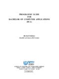
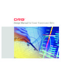
6 Thus, there is relative motion between the belt and pulley due to body slip. This is known as creep. Chain The belt drive is not a positive drive because of creep and slip. The chain drive is a positive drive. Like belts, chains can be used for larger centre distances. They are made of metal and due to this chain is heavier than the belt but they are flexible like belts. It also requires lubrication from time to time. The lubricant prevents chain from rusting and reduces wear. The chain and chain drive are shown in Figure The sprockets are used in place of pulleys. The projected teeth of sprockets fit in the recesses of the chain. The distance between roller centers of two adjacent links is known as pitch. The circle passing through the pitch centers is called pitch circle. (a) (b) (c) (d) Figure : Chain and Chain Drive Let be the angle made by the pitch of the chain, and r be the pitch circle radius, then pitch, 2 sin2pr or, cosec22pr The POWER TRANSMISSION chains are made of steel and hardened to reduce wear.
7 These chains are classified into three categories (a) Block chain (b) Roller chain (c) Inverted tooth chain (silent chain) Pin Pitch Pitch Roller Bushing Sprocket r p 83 POWER TRANSMISSION DEVICES Out of these three categories roller chain shown in Figure (b) is most commonly used. The construction of this type of chain is shown in the figure. The roller is made of steel and then hardened to reduce the wear. A good roller chain is quiter in operation as compared to the block chain and it has lesser wear. The block chain is shown in Figure (a). It is used for low speed drive. The inverted tooth chain is shown in Figures (c) and (d). It is also called as silent chain because it runs very quietly even at higher speeds. Gears Gears are also used for POWER TRANSMISSION . This is accomplished by the successive engagement of teeth. The two gears transmit motion by the direct contact like chain drive.
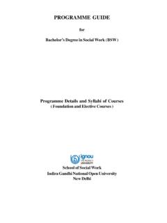
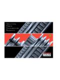
8 Gears also provide positive drive. The drive between the two gears can be represented by using plain cylinders or discs 1 and 2 having diameters equal to their pitch circles as shown in Figure The point of contact of the two pitch surfaces shell have velocity along the common tangent. Because there is no slip, definite motion of gear 1 can be transmitted to gear 2 or vice-versa. The tangential velocity Vp = 1 r1 = 2 r2 where r1 and r2 are pitch circle radii of gears 1 and 2, respectively. Figure : Gear Drive or, 1212226060 NNrr or, 1 12 2N rN r or, 1221 NrNr Since, pitch circle radius of a gear is proportional to its number of teeth (t). 1221 NtNt where t1 and t2 are the number of teeth on gears 1 and 2, respectively. SAQ 1 In which type of drive centre distance between the shafts is lowest? Give reason for this? TRANSMISSION SCREW In a screw, teeth are cut around its circular periphery which form helical path.
9 A nut has similar internal helix in its bore. When nut is turned on the screw with a force applied tangentially, screw moves forward. For one turn, movement is equal to one lead. In case of lead screw, screw rotates and nut moves along the axis over which tool post is mounted. N1 N2 2 1 VP 84 Theory of Machines Let dm be the mean diameter of the screw, be angle of friction, and p be the pitch. If one helix is unwound, it will be similar to an inclined plane for which the angle of inclination is given by (Figure ) tan Ldm For single start L = p tan pdm If force acting along the axis of the screw is W, effort applied tangential to the screw (as discussed in unit 2) tan () PW for motion against force. Also tan () PW for motion in direction of force. Figure : TRANSMISSION Screw POWER Transmitted Torque acting on the screw tan ()22 dmW dmTP If speed is N rpm POWER transmitted 2watt60 TN tan ()2kW2 60 1000 W dmN POWER TRANSMISSION BY BELTS In this section, we shall discuss how POWER is transmitted by a belt drive.
10 The belts are used to transmit very small POWER to the high amount of POWER . In some cases magnitude of the POWER is negligible but the TRANSMISSION of speed only may be important. In such cases the axes of the two shafts may not be parallel. In some cases to increase the angle L = p W P dm 85 POWER TRANSMISSION DEVICES of lap on the smaller pulley, the idler pulley is used. The angle of lap may be defined as the angle of contact between the belt and the pulley. With the increase in angle of lap, the belt drive can transmit more POWER . Along with the increase in angle of lap, the idler pulley also does not allow reduction in the initial tension in the belt . The use of idler pulley is shown in Figure Figure : Use of Idler in belt Drive SAQ 2 (a) What is the main advantage of idler pulley? (b) A prime mover drives a dc generator by belt drive. The speeds of prime mover and generator are 300 rpm and 500 rpm, respectively.