Transcription of UNIT 3 RIVETED JOINTS Riveted Joints - IGNOU
1 61 RIVETED JOINTS unit 3 RIVETED JOINTS Structure Introduction Objectives Head Forming Types of Rivets Types of RIVETED JOINTS Nomenclature Modes of Failure of a RIVETED joint Efficiency of RIVETED JOINTS Calculation of Hole Dia and Pitch RIVETED JOINTS in Structures JOINTS for Boilers and Pressure Vessels Design Procedure for Longitudinal Butt joint Design Procedure for Circumferential Lap joint Torsional Loading and Eccentric Loading of RIVETED joint Summary Key Words Answers to SAQs INTRODUCTION In engineering practice it is often required that two sheets or plates are joined together and carry the load in such ways that the joint is loaded.
2 Many times such JOINTS are required to be leak proof so that gas contained inside is not allowed to escape. A RIVETED joint is easily conceived between two plates overlapping at edges, making holes through thickness of both, passing the stem of rivet through holes and creating the head at the end of the stem on the other side. A number of rivets may pass through the row of holes, which are uniformly distributed along the edges of the plate. With such a joint having been created between two plates, they cannot be pulled apart. If force at each of the free edges is applied for pulling the plate apart the tensile stress in the plate along the row of rivet hole and shearing stress in rivets will create resisting force.
3 Such JOINTS have been used in structures, boilers and ships. The development of welding technology in 1940s has considerably reduced the RIVETED joint applications. Welding is the method of locally melting the metals (sheets or plates overlapping or butting) with intensive heating along with a filler metal or without it and allowing to cool them to form a coherent mass, thus creating a joint . Such JOINTS can be created to make structures, boilers, pressure vessels, etc. and are more conveniently made in steel. The progress has been made in welding several types of steels but large structure size may impede the use of automatic techniques and heat treatment which becomes necessary in some cases.
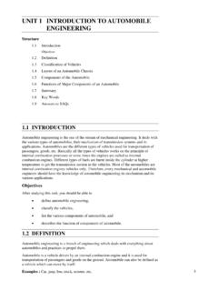
4 Welded ships were made in large size and large number during Second World War and failures of many of them spurted research efforts to make welding a better technology. Objectives After studying this unit , you should be able to describe the types of RIVETED joint , calculate the strength of RIVETED JOINTS , 62 Machine Design explain how many different ways the RIVETED JOINTS can fail, design RIVETED JOINTS for boilers, structure and under eccentric loads. HEAD FORMING You know that the RIVETED joint is created by passing the stem of a rivet through holes in two plates as is shown in Figure (a). The creation of head by process of upsetting is shown in Figure (b).
5 The upsetting of the cylindrical portion of the rivet can be done cold or hot. When diameter of rivet is 12 mm or less, cold upsetting can be done. For larger diameters the rivet is first heated to light red and inserted. The head forming immediately follows. The rivet completely fills the hole in hot process. Yet it must be understood that due to subsequent cooling the length reduces and diameter decreases. The reduction of length pulls the heads of rivet against plates and makes the joint slightly stronger. The reduction of diameter creates clearance between the inside of the hole and the rivet. Such decrease in length and diameter does not occur in cold worked rivet. ad1tt (a) (b) Figure : Typical Head Forming of Rivet TYPES OF RIVETS For steel plates the rivets are normally made in low carbon steel.
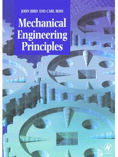
6 However, the rivets in copper add to resistance against corrosion and aluminum rivets can be used to reduce the overall weight of the structure. The low carbon steel is standardized in composition particularly for boiler applications. Rivets with counter sunk head as in Figure (b) and oval counter sunk rivets shown in Figure (c) are not as strong as button head rivets. They are used only when protrotruding rivet heads are objectionable. Pan heads and conical heads, Figures (d) and (e) are less frequently used and are difficult to form. Tubular rivets, Figures (f) and (g) are special deviation from solid rivet shank. These rivets are used in aircrafts. (b)Buton head (a)Counter sunk head (c)Oval counter sunk head(d)Pan head(e)Conical head (f)Tubular rivets(g) Figure : Different Types of Rivet Heads 63 RIVETED JOINTS TYPES OF RIVETED JOINTS The classification of RIVETED JOINTS is based on following : (a) According to purpose, (b) According to position of plates connected, and (c) According to arrangement of rivets.
7 According to purpose the RIVETED JOINTS are classified as : Strong JOINTS In these JOINTS strength is the only criterion. JOINTS in engineering structure such as beams, trusses and machine frames are strong JOINTS . Tight JOINTS These JOINTS provide strength as well as are leak proof against low pressures. JOINTS in reservoirs, containers and tanks fall under this group. Strong Tight JOINTS These are JOINTS applied in boilers and pressure vessels and ensure both strength and leak proofness. This classification has no sound basis and is arbitrary. However, it helps understand the basis of design and manufacturing. The hot working of rivets is one-way of making intimate contact between plates in the areas of joint .
8 Further, the holes are drilled and reamed to required tolerances and burrs removed for good contact before rivets are placed in the holes. The edge of the plate is upset by means of a hammer and a caulking tool so that edge is strongly pressed against the plate surface to help leak proofing (Figure ). Caulking tool 15-18o Figure : Caulking of RIVETED joint The RIVETED JOINTS are classified as (i) lap joint and (ii) butt joint according to position of plates. In a lap joint the edges of plates are simply laid over each other and RIVETED . Figures (a) and (d) show lap JOINTS . If we pull the plates by application of tensile forces, they do not fall in the same line and hence cause the rivets and plates to bend.
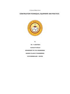
9 Plates placed end-to-end and jointed through cover plates form single cover butt joint . Such JOINTS are shown in Figures (b) and (e). You can see that pulling plates apart by colinear tensile forces may still cause bending of rivets. Figures (c) and (f) show the butting plates covered by two straps and then RIVETED . Such JOINTS are called double cover butt joint . Plate bending and rivet bending are eliminated. According to arrangement of rivets, the JOINTS are called single RIVETED , (Figures (a), (b) and (c)) It may be noted that in a single RIVETED lap joint there is only one row of rivets passing through both plates while in a single RIVETED butt joint either of single cover or double cover type one row of rivets will pass through each of the plates.
10 Similarly as shown in Figures (d) and (e) when two rows of rivets pass through both plates of lap joint it is called double RIVETED lap joint and two rows of rivets pass through each of butting plates the joint is a double RIVETED single cover butt joint . A double RIVETED double cover butt joint is shown in Figure (f). 64 Machine Design tttddddt/2(a)(b)(c)t/2 PmmmPmmdtttPmPbmPbPbPP2t Figure : Types of RIVETED JOINTS : (a) Single RIVETED Lap joint ; (b) Single RIVETED -single Cover Butt joint ; (c) Single RIVETED Double Cover Butt joint ; (d) Double RIVETED Lap joint ; (e) Double RIVETED Single Cover Butt joint ; and (f) Double RIVETED Double Cover Butt joint The arrangement of rivets in Figure (d) can be described that in both the rows the rivets are opposite to each other while in Figure (e) the rivets in the adjacent rows are staggered.