Transcription of UNIT 4 IGNITION SYSTEMS Ignition Systems
1 51 IGNITION SYSTEMS UNIT 4 IGNITION SYSTEMS Structure Introduction Objectives IGNITION System Types Comparison between Battery and Magneto IGNITION System Drawbacks (Disadvantages) of Conventional IGNITION SYSTEMS Advantages of Electronic IGNITION System Types of Electronic IGNITION System Firing Order Importance of IGNITION Timing and IGNITION Advance Summary Key Words Answers to SAQs INTRODUCTION We know that in case of Internal Combustion (IC) engines, combustion of air and fuel takes place inside the engine cylinder and the products of combustion expand to produce reciprocating motion of the piston.
2 This reciprocating motion of the piston is in turn converted into rotary motion of the crank shaft through connecting rod and crank. This rotary motion of the crank shaft is in turn used to drive the generators for generating power. We also know that there are 4-cycles of operations viz.: suction; compression; power generation and exhaust. These operations are performed either during the 2-strokes of piston or during 4-strokes of the piston and accordingly they are called as 2-stroke cycle engines and 4-stroke cycle engines. In case of petrol engines during suction operation, charge of air and petrol fuel will be taken in.
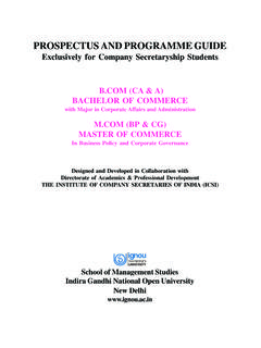
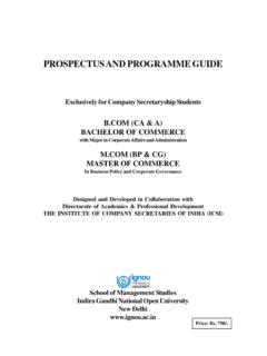
3 During compression this charge is compressed by the upward moving piston. And just before the end of compression, the charge of air and petrol fuel will be ignited by means of the spark produced by means of for spark plug. And the IGNITION system does the function of producing the spark in case of spark IGNITION engines. Spark gapMetal screwSealing washerPorceleaininsulatorContactCentral electrodeGas tightsealMetal tongue Figure : Spark Plug 52 Applied Thermal Engineering Figure shows atypical spark plug used with petrol engines. It mainly consists of a central electrode and metal tongue.
4 Central electrode is covered by means of porcelain insulating material. Through the metal screw the spark plug is fitted in the cylinder head plug. When the high tension voltage of the order of 30000 volts is applied across the spark electrodes, current jumps from one electrode to another producing a spark. Whereas in case of diesel (Compression IGNITION -CI) engines only air is taken in during suction operation and in compressed during compression operation and just before the end of compression, when diesel fuel is injected, it gets ignited due to heat of compression of air.
5 Once the charge is ignited, combustion starts and products of combustion expand, they force the piston to move downwards they produce power and after producing the power the gases are exhausted during exhaust operation. Objectives After studying this unit, you should be able to explain the different types of IGNITION SYSTEMS , differentiate between battery and magneto IGNITION system know the drawbacks of conventional IGNITION system, and appreciate the importance of IGNITION timing and IGNITION advance. IGNITION SYSTEM TYPES Basically Convectional IGNITION SYSTEMS are of 2 types : (a) Battery or Coil IGNITION System, and (b) Magneto IGNITION System.
6 Both these conventional, IGNITION SYSTEMS work on mutual electromagnetic induction principle. Battery IGNITION system was generally used in 4-wheelers, but now-a-days it is more commonly used in 2-wheelers also ( Button start, 2-wheelers like Pulsar, Kinetic Honda; Honda-Activa, Scooty, Fiero, etc.). In this case 6 V or 12 V batteries will supply necessary current in the primary winding. Magneto IGNITION system is mainly used in 2-wheelers, kick start engines. (Example, Bajaj Scooters, Boxer, Victor, Splendor, Passion, etc.). In this case magneto will produce and supply current to the primary winding.
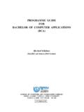
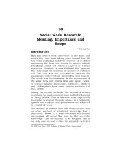
7 So in magneto IGNITION system magneto replaces the battery. Battery or Coil IGNITION System Figure shows line diagram of battery IGNITION system for a 4-cylinder petrol engine. It mainly consists of a 6 or 12 volt battery, ammeter, IGNITION switch, auto-transformer (step up transformer), contact breaker, capacitor, distributor rotor, distributor contact points, spark plugs, etc. Note that the Figure shows the IGNITION system for 4-cylinder petrol engine, here there are 4-spark plugs and contact breaker cam has 4-corners. (If it is for 6-cylinder engine it will have 6-spark plugs and contact breaker cam will be a perfect hexagon).
8 The IGNITION system is divided into 2-circuits : (i) Primary Circuit : It consists of 6 or 12 V battery, ammeter, IGNITION switch, primary winding it has 200-300 turns of 20 SWG (Sharps Wire Gauge) gauge wire, contact breaker, capacitor. 53 IGNITION SYSTEMS (ii) Secondary Circuit : It consists of secondary winding. Secondary winding consists of about 21000 turns of 40 (S WG) gauge wire. Bottom end of which is connected to bottom end of primary and top end of secondary winding is connected to centre of distributor rotor. Distributor rotors rotate and make contacts with contact points and are connected to spark plugs which are fitted in cylinder heads (engine earth).
9 (iii) Working : When the IGNITION switch is closed and engine in cranked, as soon as the contact breaker closes, a low voltage current will flow through the primary winding. It is also to be noted that the contact beaker cam opens and closes the circuit 4-times (for 4 cylinders) in one revolution. When the contact breaker opens the contact, the magnetic field begins to collapse. Because of this collapsing magnetic field, current will be induced in the secondary winding. And because of more turns (@ 21000 turns) of secondary, voltage goes unto 28000-30000 volts.
10 CoilPrimarywinding(200 - 300 turns of20 gauge wire)Secondarywinding(2100 turns of40 gauge wire)(20000 - 30000 V)DistributorcontactsIgnitionswitchAmmet erContactBreakerBattery(6 or 12V)Contact breakeroperating camDistributorSparkplugs1234 Capacitor Figure : Schematic Diagram of Coil/Battery IGNITION System This high voltage current is brought to centre of the distributor rotor. Distributor rotor rotates and supplies this high voltage current to proper stark plug depending upon the engine firing order. When the high voltage current jumps the spark plug gap, it produces the spark and the charge is ignited-combustion starts-products of combustion expand and produce power.