Transcription of Universal Accumulator Charging Kit - STAUFF
1 Local Solutions For Individual Customers WorldwideUniversal Accumulator Charging KitBladder and DiaphragmInstruction ManualDescription 4 Safety Instructions & Recommendations 4 Connection Flow Chart 5 Checking the Pre-charge Pressure 6 Service Options 6 Pre- Charging Accumulator Instructions 7 Applying the Pre-charge Pressure 7 Maintenance of the STA-CK Charging Valve 7 Gas Pressure Change According to Temperature Variation 8 Components Layout 9 Component Contents 10 Universal Charging Kit Instruction ManualUniversal Charging Kit Accumulator Charging KitOperating and Maintenance InstructionsDescriptionSTAUFF's Universal Accumulator Charging kit is an essential instrument for the verification, pressurisation and gas bleeding of hydraulic accumulators , suitable for most common bladder and diaphragm standard kit is delivered in a storage case containing the following.
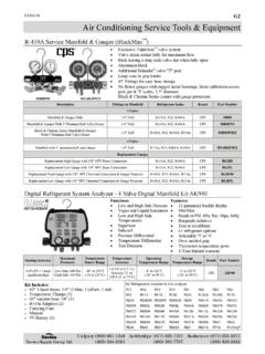
2 1 1 x Charging head for testing and pressurising (swivel connection M28 x )2 1 x Adaptor 1/4" BSPP3 1 x Adaptor 5/8" - 18" UNF4 1 x Adaptor (long) 7/8" - 14" UNF6 1 x Adaptor (short) Integrated 7/8" - 14" UNF8 1 x 0 - 100 bar safety pattern pressure gauge + adaptor SMD20G1/4"9 1 x 0 - 250 bar safety pattern pressure gauge + adaptor SMD20G1/4"J 1 x Adaptor 5/8" - 18" UNF - "K 1 x High pressure gas hose (2000 mm long) for connecting to a nitrogen gas source SKK20-1/4" BSPP femaleL 1 x Safety gogglesM 1 x Hex key 6 mmN 1 x Operating instructionsOptional5 Type 51 gas bottle adaptor7 Type 50 gas bottle adaptorAvailable on request 0 - 400 bar kitApplication For checking and pre- Charging common types of accumulators Maximum working pressure of this equipment (excluding individual pressure rating of gauges) is 400 Instructions and Recommendations 1.
3 Before using the Charging head carefully read the directions and safety instructions in this guide. 2. In all cases observe the pressure limits indicated on the Accumulator pressure vessels. If necessary refer to the applicable operating instructions. 3. Before attempting to check the pre-charge pressure, the Accumulator in the hydraulic circuit under pressure has to be isolated and discharged on the hydraulic side. If required immobilize it and define a safety zone. 4. Only use nitrogen gas with a purity 99,8% (N2) to pressurise the Accumulator . 5. STAUFF always recommends the use of a nitrogen gas regulator on the nitrogen gas bottle. 6. The Charging valve (1) and pressure gauge (3) are tools for checking gas pressure and pre- Charging accumulators .
4 In cases where the gauge and gauge adaptor will be left on the Accumulator , make sure that the gauge fitted is rated for the maximum system pressure of the hydraulic circuit. 7. Never use an Accumulator in a hydraulic system without it first being pre-charged with the correct nitrogen gas pressure. Failure to do this will result in bladder or diaphragm damage. 8. Ensure safety goggles are worn when either checking or pre- Charging accumulators . 9. To ensure optimum efficiency and performance of the hydraulic circuit, the pre-charge pressure must be checked frequently. STAUFF recommends the pressure be checked initially at intervals of 1 month, 3 months and then 6 months after installation.
5 Depending on the amount of loss of pressure (if any) over this time, a planned maintenance schedule for monitoring the pressure can then be put into operation (check annually). Only use gas approved" test hose For use with nitrogen (N2) gas only Safety goggles must be worn at all times STAUFF pressure gauges are safety pattern type according to Charging Kit Connection Flow ChartDirect connection toM28 dia x Accumulator valve with 6 mm A/FHexagonal socket - head screw " x 32 TPI threaded or not threaded Adaptor (4) connects directly to 7/8" UNF Bladder StemHydac / Bosch Rexroth / ParkerAdaptor (long)7/8" - 14" UNFA daptor (short)7/8" - 14" UNFA daptor5/8" - 18" UNFA daptor5/8" - 18" UNFType 51 Gas Bottle Adaptor(optional)
6 High Pressure Gas Hose DN4 Charging HeadSet of AdaptorsSafety Pattern Pressure GaugeAdaptor5/8" - " x 32 TPI US Style Gas ValveAdaptor1/4" BSPP1/2" UNF Integrated Valve Adaptor (6) connects directly to 7/8" UNF Bladder StemOlaer / STAUFF5/8" UNF Male Thread Adaptor (3) connects directly to 5/8" UNF Gas ValveEuropean - " x 32 TPI Threaded US Style Valve Adaptor (3) connects via 5/8" UNF and " x 32 TPI (10)US Style Gas Valve1/4" BSPP Male Thread Adaptor (2) connects directly to 1/4" BSPP Gas ValveOlaer / Fawcett Christie / STAUFFD irect Gauge Adaptor - SMDL ength: 2000 mm7/8"-14" UNF7/8"-14" UNF5/8"-18" UNFM28F x "-18" UNF1/4" BSPPABDEEFCDGGGGGGType 50 Gas Bottle Adaptor(optional)Use of a regulator is recommend1 2 J 3 3 6 4 Universal Charging Kit the Pre-charge PressureService OptionsGeneral 1.
7 Recommendation: Before proceeding to any operation concerning the initial pressurisation of an Accumulator , consult the applicable operating instructions. 2. Pressurisation limits: Ensure that the Universal Accumulator Charging Kit and any associated pressure gauge fitted are rated for the intended pressure for both pre- Charging and pressure checking. Refer to the manufacturers specifications. The nitrogen gas pressure varies as a function of the gas temperature. After each inflation and deflation of nitrogen gas, wait for the temperature to stabilise before checking the pressure (this may take several minutes depending on the Accumulator size).
8 Never exceed the maximum stated design pressure (PS or DP) of the Accumulator as stamped on the vessel. If in doubt consult the manufacturer or check manufacturer s operating instructions or specifications manual. Bladder AccumulatorsRefer to page 5 for connection flow chart Remove the protection or gas valve cap fitted to the gas side of the Accumulator Select the adaptor according to the gas valve fitted to the Accumulator (4 or 6), (3+10), (3 or 2) Ensure the pin in the adaptor is backed off by unscrewing the socket head cap screw (G) in an anti-clockwise direction. To do this use the 6 mm hex key supplied in the Charging kit Attach the appropriate adaptor to the Accumulator gas valve Take the Charging head (1) from the kit and install the pressure gauge by attaching it to the test coupling (E).
9 Make sure the pressure gauge is compatible with the gas pressure (to be verified) and make sure the bleed valve (C) is closed Manually tighten the knurled ring (B) on the Charging head (1) to the adaptor (4 or 6), (3+10), (3 or 2), positioning the device in such a way that the pressure gauge values can be easily read Open the Accumulator gas valve by slowly tightening (clock-wise) the lobe wheel (A) until the pre-charge pressure is indicated on the pressure gauge. DO NOT overtighten the lobe wheel (A)Diaphragm AccumulatorsRefer to page 5 for connection flow chart When checking the pre-charge pressure of a diaphragm Accumulator fitted with a 6 mm socket head cap screw carefully loosen the socket head cap screw (G) by turning anti-clockwise to relieve any tension Take the Charging head (1) from the kit and install the pressure gauge by attaching it to the test coupling (E).
10 Make sure the pressure gauge is compatible with the gas pressure (to be verified) and make sure the bleed valve (C) is closed Mount the Charging head (1) directly to the Accumulator s M28 threaded connection (no adaptor required), by tightening the knurled ring (B) on the Charging head Once the Charging head (1) is connected to the Accumulator , unscrew the lobe wheel (A) anti-clockwise until the inflation pressure is indicated on the pressure gaugeOption 1. The displayed nitrogen gas pressure (P0) is correctRefer to page 5 for connection flow chart For bladder accumulators manually unscrew the lobe wheel (A) anti-clockwise. The lobe wheel (A) allows re-closing of the gas valve For diaphragm accumulators manually screw the lobe wheel (A) clockwise.