Transcription of Universal TAU-IIR Redirective, Non-Gating, Crash …
1 - 1 - Product Specification Universal TAU-IIR redirective , Non- gating , Crash Cushion I. General The Universal TAU-IIR system is a redirective , Non- gating Crash Cushion in accordance with the definitions in the National Cooperative Highway Research Program Report 350 (NCHRP Report 350) that uses re-useable and restorable energy absorbing elements (EAE). The system has been tested in narrow and wide configurations and performs in an acceptable manner in accordance with the guidelines of NCHRP Report 350 at Test level 2 (70 km/h) and Test Level 3 (100 km/h).
2 The system performs acceptably in various configurations for different impact velocities and hazard widths. These configurations are shown in the Universal TAU-II System Configuration Chart (Figure 1). II. Performance The Universal TAU-IIR system is designed to absorb the impact energy of an errant vehicle in accordance with NCHRP Report 350 guidelines for redirective , Non- gating Crash cushions . The system is designed for locations where both head-on and angled impacts are likely to occur and where it is desirable to have the majority of post impact trajectories on the impact side of the system.
3 The design provides for a high degree of flexibility in applying the system to a wide range of hazard widths (up to meters ( feet)) in 150mm (6 inch) increments and a large variety of non-proprietary transitions to other highway barriers and structures. When installed in accordance with the manufacturer s instructions, the configurations shown in the Configuration Chart (Figure 1) under the 100 km/h ( mph) column are capable of safely redirecting or stopping a 2000 kg (4400 lb) pick-up truck or a 820 kg (1800 lb) car impacting the system at 100 km/hr ( mph) within the angles set forth in NCHRP Report 350.
4 A. When properly installed according to the manufacturer s specifications, the systems shall be able to meet the recommended structural adequacy, occupant risk, and vehicle trajectory criteria set forth in NCHRP 350 for Test Level 3 (100 km/hr) redirective , Non- gating Crash cushions . The NCHRP 350, Test Level 3 Test Matrix includes the following conditions: TB 110927 Rev. 0 Page 1 of 5 - 2 - 1. An 820 kg vehicle at 0 degrees and an offset of the width of the vehicle from the centerline of the system (Test 3-30). 2. A 2000 kg vehicle at 0 degrees and centered on the front of the system (Test 3-31).
5 3. An 820 kg vehicle at 15 degrees impacting the front of the system (Test 3-32). 4. A 2000 kg vehicle at 15 degrees impacting the front of the system (Test 3-33). 5. An 820 kg vehicle at 20 degrees impacting the side, near the front of the system (Test 3-36). 6. A 2000 kg vehicle at 20 degrees impacting the side, near the front of the system (Test 3-37). 7. A 2000 kg vehicle at 20 degrees impacting at the Critical Impact Point of the system. The critical impact point was determined to be the front of the backstop along the centerline of the system (Test 3-38).
6 8. A 2000 kg vehicle at -20 degrees (reverse direction) impact to the midpoint of the system (Test 3-39). B. The impact velocity of a hypothetical front seat passenger against the vehicle interior as calculated from the longitudinal vehicle acceleration and 600 mm [23 5/8 in] forward displacement, and the lateral vehicle acceleration and 300 mm [12 in] lateral vehicle displacement, shall be less than 12 m/s ( ft/s). The highest 10 ms average vehicle acceleration in the longitudinal and lateral directions subsequent to the instant of hypothetical occupant impact shall be less than 20 g s in the NCHRP 350 testing matrix of the Universal TAU-IIR system.
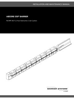
7 Detached debris shall not show potential for penetrating the vehicle occupant compartment or present a hazard to other traffic, pedestrians, or workers in a work zone. The vehicle shall remain upright during and after the collision, although moderate roll, pitch, and yaw may occur. Vehicle deformations shall not cause intrusion into the occupant compartment in excess of 150 mm (6 inches). III. Description of System A. The Universal TAU-IIR Crash cushion is made up of independent collapsible bays that are guided and supported by high strength galvanized steel cables.
8 The system s energy capacity is provided by an array of re-useable and - 3 - restorable EAE. The systems shall be made up of the following components and shall be fabricated from materials conforming to the following specifications: 1. The foundation system for the Universal TAU-IIR consists of two cables, a Back Support and Front Cable Anchors as shown in Figure 2 or Figure 3. The Front Cable Anchor weighs approximately 35 kg (75 lb). The types of Cable Anchors and Back Supports can be selected based on the requirements of the specific site. a.
9 All steel structural components of these assemblies shall be fabricated from mild steel in conformance with ASTM A-36 specifications. These components are hot dipped galvanized per ASTM A-123. b. Fasteners shall be Class (Grade 2) or greater and galvanized in accordance with ASTM 153 or ASTM B695, Class 50. Washers shall be hardened and galvanized. c. The steel cables shall be at least 25 mm (1 in) diameter and galvanized in accordance with ASTM A-603. 2. Front and Middle Supports and the various sizes of Bulkheads (XL, XXL and XXXL) (Figure 2) separate each independent collapsible bay.
10 Cable Guides bolt to the Middle Supports and Bulkheads, capturing the cables and connecting the bays to the foundation system. a. All Front and Middle Supports, Bulkheads and cable guides shall be fabricated from mild steel in conformance with ASTM A-36 specifications. These components are hot dipped galvanized per ASTM A-123. b. All fasteners shall be Class (Grade 2) or greater and galvanized in accordance with ASTM 153 or ASTM B695, Class 50. Washers shall be hardened and galvanized. 3. Each Bay is enclosed on the sides with Sliding Panels.